
| Version 14 (modified by , 13 years ago) ( diff ) |
|---|
Table of Contents
Orbit Power Monitoring
(By: Pavan A. Desai)
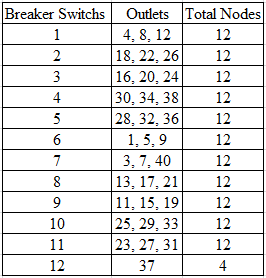
Goal: The overall goal of this project is to measure and monitor the power consumption across each node in the ORBIT test bed by effectively mapping each node to the proper breaker switch on the breaker board.
Requirements:
- Mega Arduino Board (Need both Arduino hardware & software for processing purposes)
- Arduino Ethernet Shield (Need to connect the Arduino Board to different networks)
- ORBIT Power Sensing Platform (Need to measure power)
- PuTTY Pageant Software (Used to connect to ORBIT's "Grid Network" from ones PC to observe the collection of data)
- PuTTY SSKEY (Used to create a secure shell key for secure data communication, PuTTY Pageant will require it for all ORBIT network connections)
- Ruby (Will be needed to parse XML output)
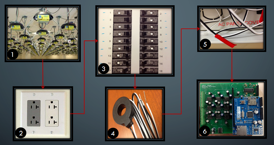
Overall Operation:

|
| Figure 1: Full View |
1) Total of 4 nodes are connected to one outlet.
2) 2-3 Outlets are connected to a single breaker switch.
3) On the breaker board there is a toroid connected behind each breaker switch.
4) A Brultech Micro-40 Donut Style toroid is used to scale down the current at a ratio of 40A to 26.23mA.
5) The ends of the toroid sensors are connected to the ORBIT Power Sensing Platform.
6) The ORBIT Power Sensing Platform is connected to the Arduino board and shield.
Power Sensing Platform:

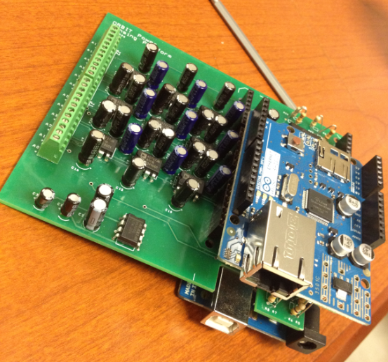
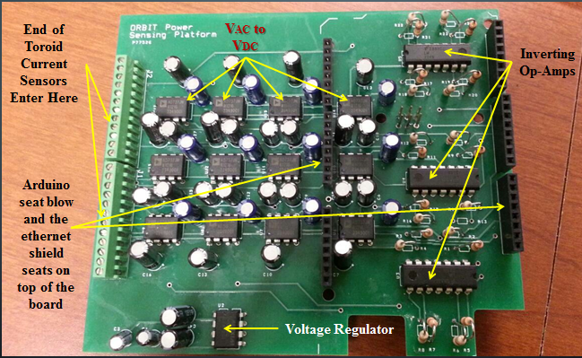
|
| Figure 2: Sensor Board |
Once the current is stepped down by the toroid, a 42Ω resister is used to convert the AC current into AC voltage at the entrance of the Power Sensing Platform. Then the AC voltage is converted to DC voltage by going through AD737JNZ chip with a average off-set of 3.364mV between the input and output of the chip. The voltage regulator is used to lower the voltage that powers the AD737JNZ chip to values of ± 2.5V from ± 3.3V. The inverting amplifier with a gain of 4.7 is used to convert the negative voltage value outputted from the AD737JNZ chip to a positive value because the Arduino does not accept negative inputs. Once the signal enters the Arduino analog pins, the Arduino will read the signal at the analog pin and output a resolution reading between 0 to 1023. The Arduino has a 10-bit analog to digital converter (ADC) so it will map input voltages between 0 and 5 volts into integer values between 0 and 1023. In this project I have used the internal built in voltage of 1.1V instead of the normal 5V in the Arduino board. This change will map the resolution reading between 0 to 1023 for 0 to 1.1V. Then the software part of this project will fix the off-set of the AD737JNZ chip and the scaling factor of the toroid along with adjusting the Arduino to covert the resolution readings to power readings.
Procedure:
1) Connect the Arduino board and Arduino Ethernet Shield to the ORBIT Power Sensing Platform. The Arduino board will be connected to the bottom of the ORBIT Power Sensing Platform and the Arduino Ethernet Shield will be place on the top of the ORBIT Power Sensing Platform as shown below:

|
| Figure : Connection |
2) Upload the following code to the Arduino board from the attachments:
PowerSensingCode.inoNote: MAC & IP Address will have to be changed for futuresensors along with AD737JNZ chip off-set for each analog pin and proper toroid scaling ratio.
3) Calculations inside the code:
if (analogChannel == 0)
   {double d= 0.0;
      d = static_cast<double>(sensorReading);
      double power = 42 * square((((((((sensorReading/1024.0)*1100.0)/4.700)+2.468)/42)*40)/0.02623)/1000);
      client.print(power); // Prints out Power Reading in Watts

    //double voltage = (((sensorReading/1024.0)*1100.0)/4.700+2.468);  //Prints out Voltage Reading
    //client.print(voltage); // Prints out Voltage Reading in Volts
   }
The calculations shown above are only for analog pin 0 out of 12 analog pins, the rest of the pins have similar calculations. When the output from the Power Sensing Platform enters the input of the Arduino board its resolution reading is called the "sensorReading." The sensorReading value is a resolution reading between 0 to 1023 for 1100mV (1.1V), that needs to be converted to double datatype from a integer datatype to proceed with further calculations which are in double datatype.
((((sensorReading/1024.0)*1100.0)/4.700)+2.468)
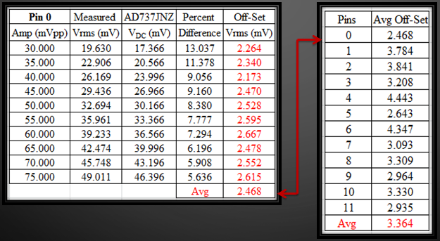
First convert the resolution reading into voltage reading by taking the ratio of the resolution reading and multiplying it by 1100mV internal Arduino voltage. Then by dividing out the inverting amplifier gain of 4.7 and adding the AD737JNZ chip off-set of 2.468mV gives us a final voltage reading of the input signal. The off-set for the AD737JNZ chip was calculated individually for each analog pin by testing 10 different AC signals and measuring the input and output of the AD737JNZ chip.

|
| Figure : Chip Off-Set |
To view rest of the off-sets download
Off-Set-Chart.xlsxfrom the attachments. The next step is to convert this voltage reading to a current reading by dividing the voltage by 42Ω. Now the current has to be scaled back again by applying the inverse ratio of 40A to 26.23mA to the code and lastly converting the proper current reading to a power reading by the applying the following equation: P = I*I*R. This code will output the data on the web server in XML format.
4) Use PuTTY Pageant Software to double tunnel to the proper network within the ORBIT network. PuTTY SSKEY will be required.
5) Locate the sensor by the IP address in the network and parse its XML with Ruby began to collect data.
Current Progress:
Attachments (10)
- board.PNG (795.5 KB ) - added by 13 years ago.
- Overview1.PNG (649.3 KB ) - added by 13 years ago.
- Power Sensing Platform.PNG (790.4 KB ) - added by 13 years ago.
- powersensor.PNG (716.4 KB ) - added by 13 years ago.
- PowerSensingCode.ino (14.8 KB ) - added by 13 years ago.
- Off-Set-Chart.xlsx (21.3 KB ) - added by 13 years ago.
- IndepPinOff-Set.PNG (122.7 KB ) - added by 13 years ago.
- Node Mapping.PNG (56.3 KB ) - added by 13 years ago.
- Mapping Results.PNG (8.4 KB ) - added by 13 years ago.
- Mapping Data.xlsx (16.6 KB ) - added by 13 years ago.