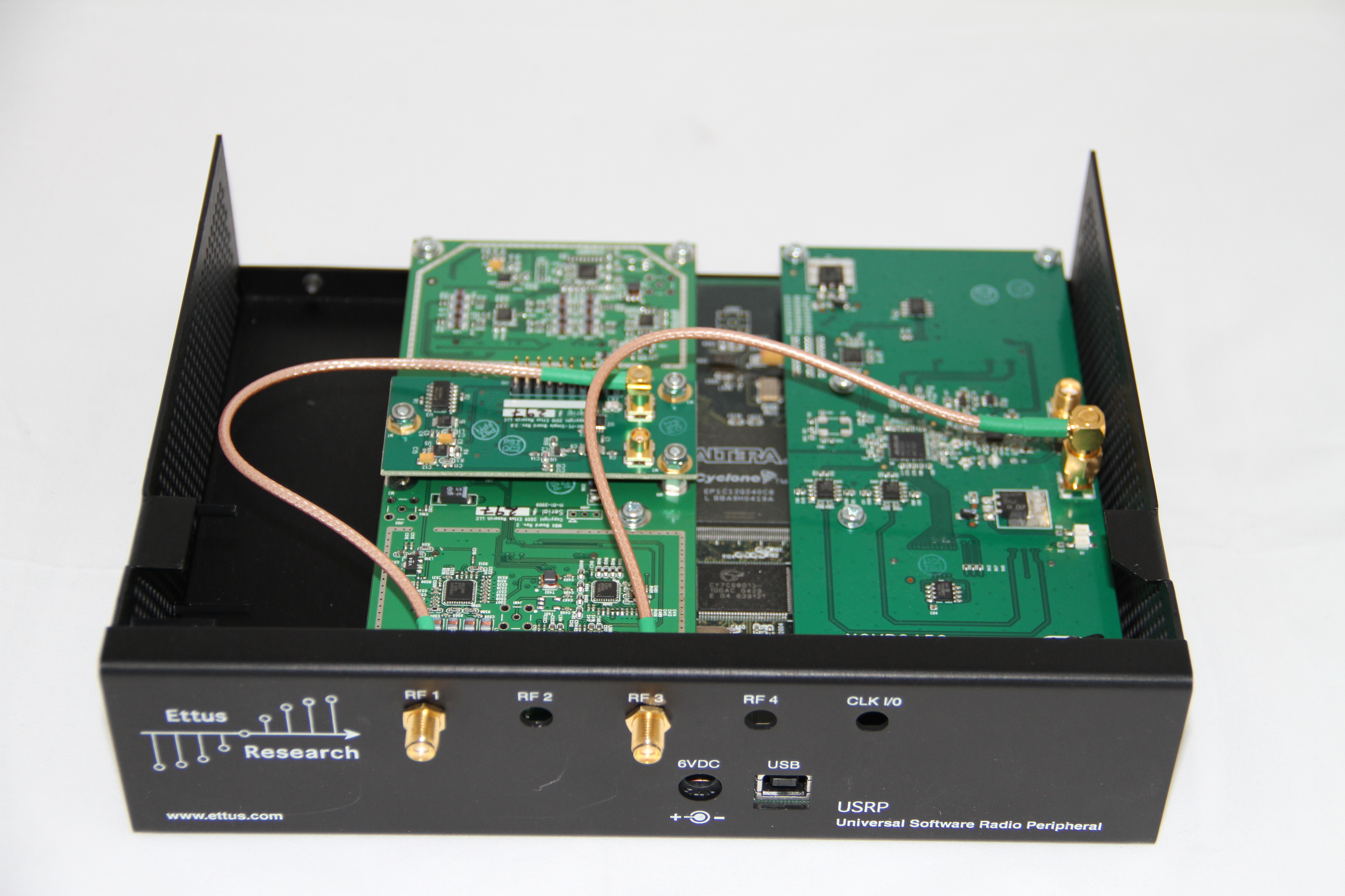
USRP 1
USRP N210
USRP X310
USRP B210
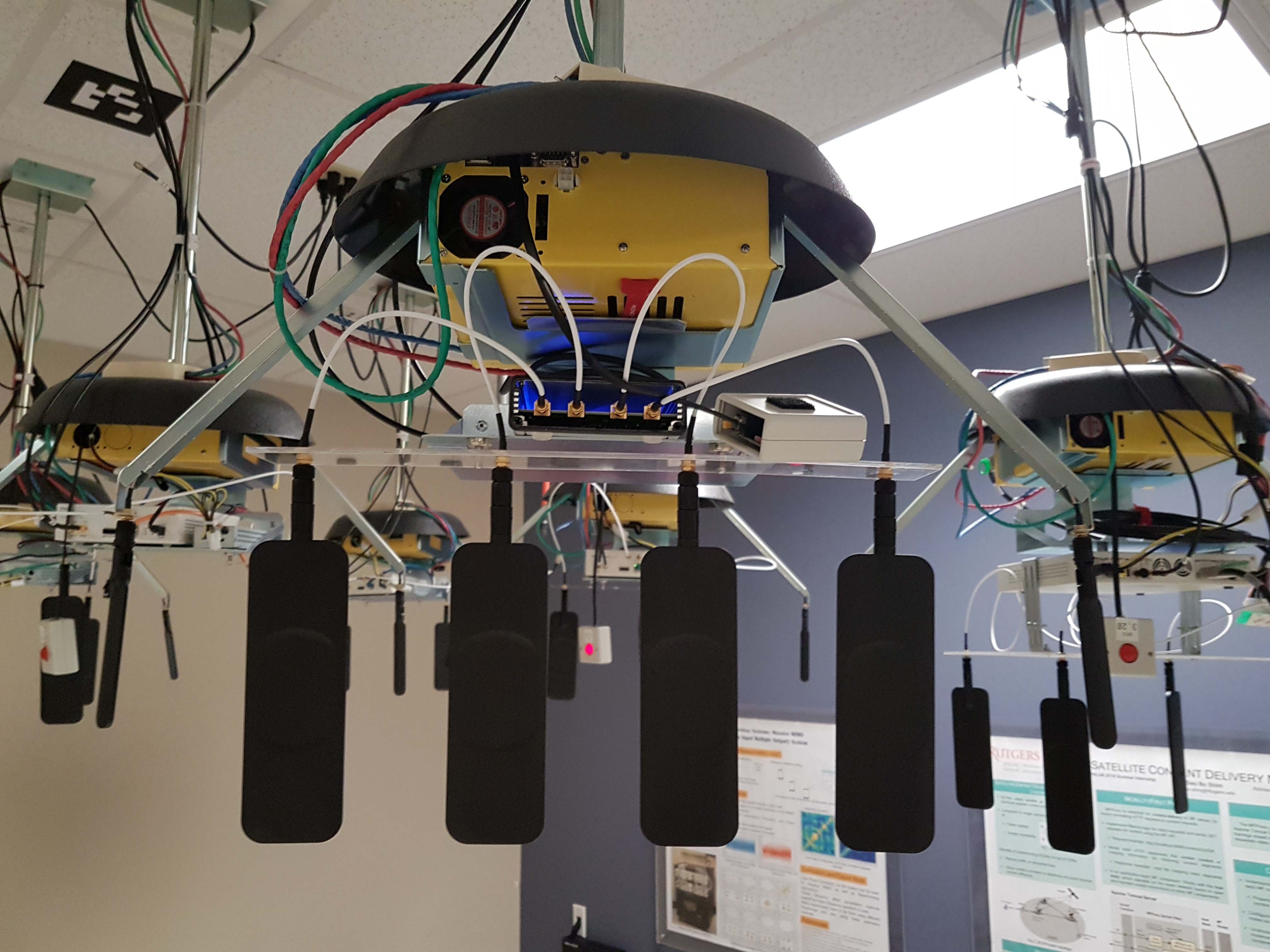
ORBIT USRP Deployment
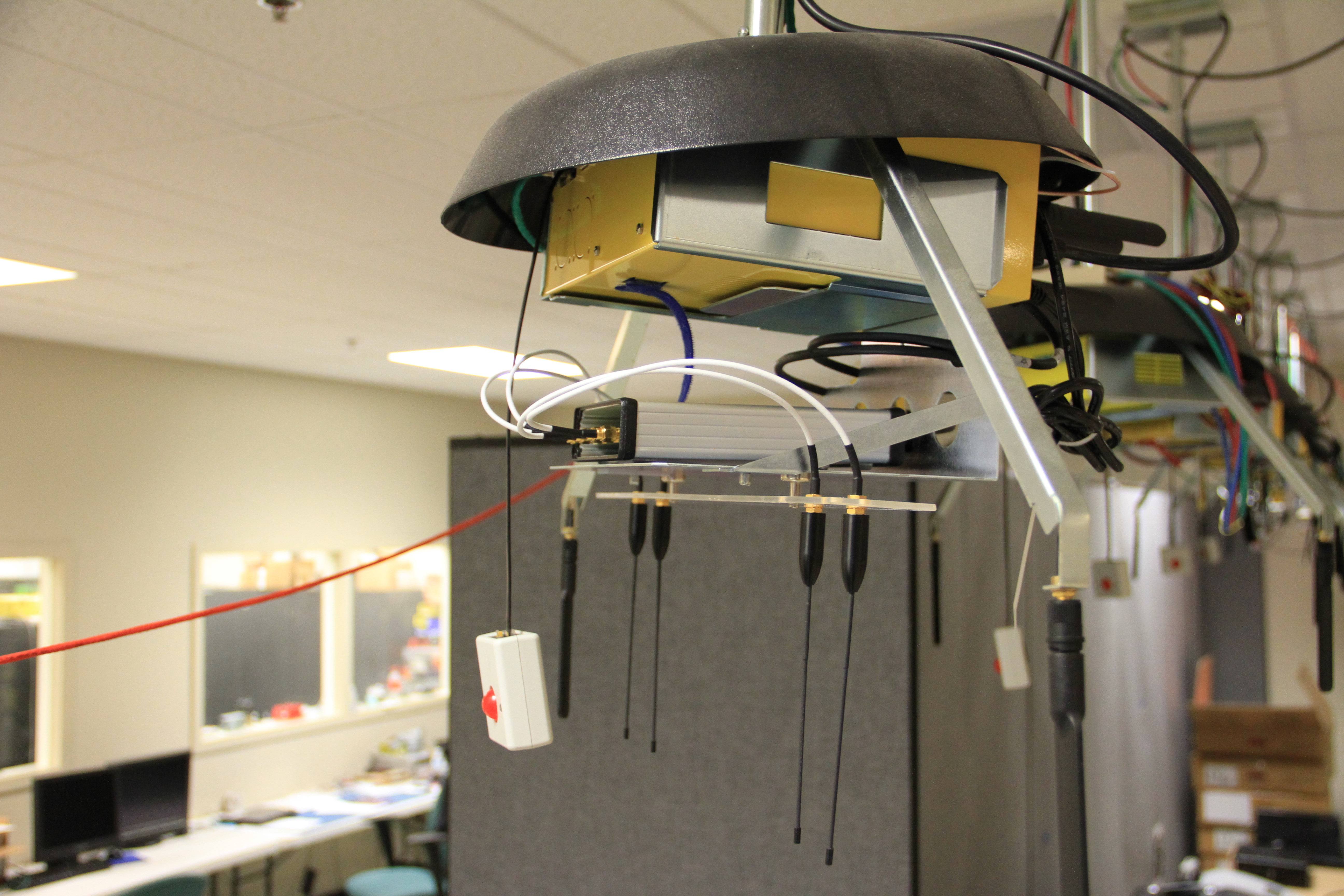
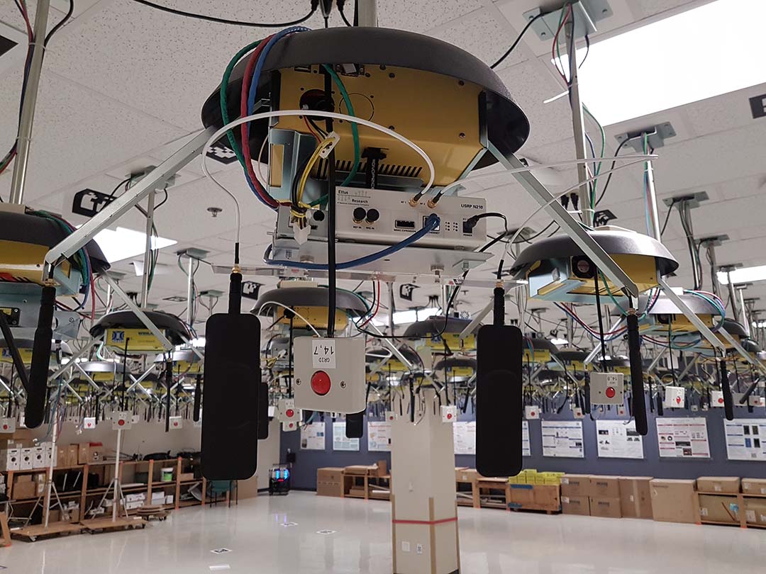
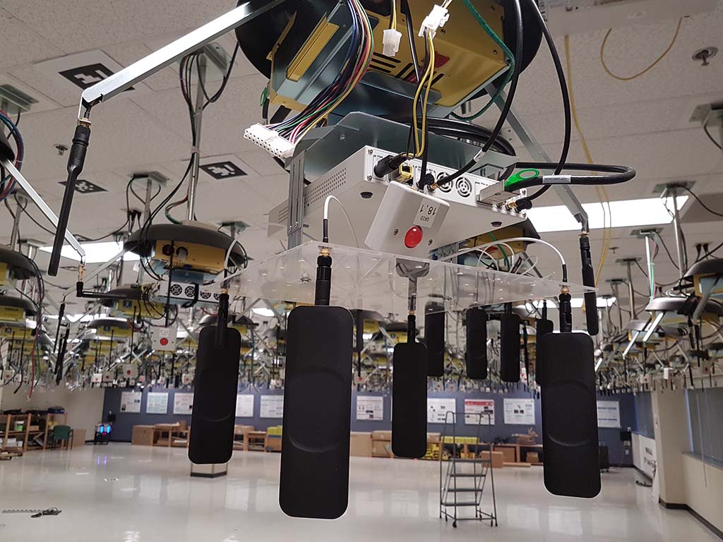
The majority of SDR devices in the ORBIT grid are various generations of Universal Software Radio Peripherals (USRP) . Each USRP, whether USB or Ethernet based, is attached to a generation 3 node and is physically located on a small shelf immediately underneath the node (as shown in the antenna table below).
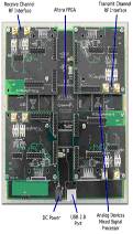
In the case of USRP devices, the USB interface is attached to one of the USB2 ports on a corresponding node. For USRP2s (and N210s), the Ethernet interface of each device is connected to a (third) dedicated Ethernet interface on the node (eth2) that is used solely for USRP related communication.
The USRP X310s are attached to the new generation 4 nodes. They are attached to a 10 Gigabit NIC on the node via SFP+ direct attach cable, and are attached via fiber to our aggregate switch. (Note, fiber link is still undergoing testing/debugging.)
The nodes with USRP devices are distributed through the grid as shown in the deployment table. In addition to grid deployment two sandboxes are available for development: sandbox3 is equipped with two USRP2s, while sanbox5 has two USRPs attached.
USRP Antenna Mounting
| USRP | USRP2 / USRP N210 | USRP X310 | USRP B210
|
 |  | |
|
USRP Deployment Maps
GRID
| Node Coordinate | Device type | RF Daughter Boards (side A) | RF Daughter Boards (side B)
|
| [18,20] | USRP X310 | SBX120 | CBX120
|
| [3,20] | USRP X310 | SBX120 | CBX120
|
| [18,1] | USRP X310 | SBX120 | CBX120
|
| [3,1] | USRP X310 | SBX120 | CBX120
|
| [3,2] | B210 | - | -
|
| [3-19] | B210 | - | -
|
| [8,7] | B210 | - | -
|
| [8,14] | B210 | - | -
|
| [13,7] | B210 | - | -
|
| [13,14] | B210 | - | -
|
| [18,2] | B210 | - | -
|
| [18,19] | B210 | - | -
|
| [1,1] | USRP2 N210 | SBX | -
|
| [1,2] | USRP2 N210 | SBX | -
|
| [2,1] | USRP2 N210 | SBX | -
|
| [2,2] | USRP2 N210 | SBX | -
|
| [1,19] | USRP2 N210 | SBX | -
|
| [1,20] | USRP2 N210 | SBX | -
|
| [2,19] | USRP2 N210 | SBX | -
|
| [2,20] | USRP2 N210 | SBX | -
|
| [7,7] | USRP2 N210 | SBX | -
|
| [7,14] | USRP2 N210 | SBX | -
|
| [8,8] | USRP2 N210 | SBX | -
|
| [8,13] | USRP2 N210 | SBX | -
|
| [11,10] | USRP2 N210 | SBX | -
|
| [13,8] | USRP2 N210 | SBX | -
|
| [13,13] | USRP2 N210 | SBX | -
|
| [14,7] | USRP2 N210 | SBX | -
|
| [14,14] | USRP2 N210 | SBX | -
|
| [19,1] | USRP2 N210 | SBX | -
|
| [19,2] | USRP2 N210 | SBX | -
|
| [20,1] | USRP2 N210 | SBX | -
|
| [20,2] | USRP2 N210 | SBX | -
|
| [19,19] | USRP2 N210 | SBX | -
|
| [19,20] | USRP2 N210 | SBX | -
|
| [20,19] | USRP2 N210 | SBX | -
|
| [20,20] | USRP2 N210 | SBX | -
|
| [3,3] | USRP | XCVR2450 | WBX
|
| [3,18] | USRP | XCVR2450 | WBX
|
| [6,6] | USRP | XCVR2450 | WBX
|
| [6,15] | USRP | XCVR2450 | WBX
|
| [10,10] | USRP | XCVR2450 | WBX
|
| [16,5] | USRP | XCVR2450 | WBX
|
| [15,15] | USRP | XCVR2450 | WBX
|
| [18,3] | USRP | XCVR2450 | WBX
|
| [18,18] | USRP | XCVR2450 | WBX
|
SB1
| Node Coordinate | Device type | RF Daughter Boards (side A) | RF Daughter Boards (side B)
|
| [1,1] | B210 | - | -
|
| [1,2] | B210 | - | -
|
SB2
SB3
SB5
SB7


