
Table of Contents
Last updated: 2021/07/26
Working with USRP X310
Description
For this tutorial, we will now use two USRP X310s on ORBIT Sandbox 2 to transmit and receive a single frequency over the air to demonstrate the use of the USRP Hardware Drivers (UHD) and GNU Radio with the USRP X310. This tutorial can be run on other USRP X310s available of the grid as well. For details on available USRPs on the grid, please see available USRP hardware in the grid.
As with any of these tutorials, it is much more productive to write the commands by hand rather than just copy-paste them. This will help memorize what is going on.
Hardware / Software Resources Utilized
We will be using the X310 radios in ORBIT Sandbox 2. One radio will be used to transmit, and the other to receive. For more information on these radios, please see the Sandbox 2 page.
We will use the following node image: ubuntu1804-uhd3.15-gr3.8.ndz which contains UHD 3.15.0 along with GNU Radio 3.8.
Set Up
Imaging
First, make sure you have Sandbox 2 reserved and are logged into the console over SSH. Please enable X11 forwarding, by using the -X flag (-Y if on Mac OS) in your SSH command.
We should make sure that both of the nodes are turned off:
mpk2138@console:~$ omf tell -a offh -t node1-1,node1-2
Then, we want to image the nodes with the following commands:
mpk2138@console:~$ omf load -i ubuntu1804-uhd3.15-gr3.8.ndz -t node1-1,node1-2
Please note, it will take time to image the node, make sure that the first image process is finished before attempting to start the second.
Once both nodes are imaged, we can now turn them back on:
mpk2138@console:~$ omf tell -a on -t node1-1,node1-2
Accessing the Nodes
Give the node about a minute to turn on and be ready, and then SSH into the first node:
mpk2138@console:~$ ssh -X root@node1-1
Once you have SSH'd into node1-1, open a second SSH session and login to the Sandbox 2 console as before. On that new SSH session, SSH into the other node:
mpk2138@console:~$ ssh -X root@node1-2
At this stage, you should have two SSH windows open, each logged into one of the two nodes.
Configuring the Network Interface
Each node is physically connected to one USRP X310 over a 10 Gbps Ethernet connection. However, the default network card interface configuration will need to be changed so that the node can communicate to the correct IP address.
The USRP X310 uses a default IP address of 192.168.40.2 on its first 10 Gbps interface, which is the interface being used to connect to the node. So on both nodes, run the following command to edit the network interface netplan file to use the correct IP address:
root@node1-X:~# cd /etc/netplan/
root@node1-X:/etc/netplan# rm -rf 00-netplan-ifrename.yaml
root@node1-X:/etc/netplan# systemctl disable ifrename.service
root@node1-X:/etc/netplan# cp 00-netplan.yaml.bak 00-netplan.yaml
root@node1-X:/etc/netplan# nano 00-netplan.yaml
Add the following lines to the end of the file that we opened with nano (Remember, indentation matters and you must use spaces, not tabs):
    enp1s0:
      dhcp4: false
      addresses: [192.168.40.1/24]
And now your netplan file should look like this:
network:
  version: 2
  renderer: networkd
  ethernets:
    wired:
      match:
        name: en*
      dhcp4: true
      optional: true
    enp1s0:
      dhcp4: false
      addresses: [192.168.40.1/24]
Apply the new configuration
root@node1-X:/etc/netplan# netplan apply
and then exit node1-X to console and reboot the node to make the netplan we just set be fully applied:
root@node1-X:/etc/netplan# exit
username@console:~$ omf tell -a reset -t node1-X
username@console:~$ ssh -X root@node1-X
install net-tools by running:
root@node1-X:~# apt install net-tools
verify the netplan settings have been applied by running:
root@node1-X:~# ifconfig
and you should see something like this:
enp1s0: flags=4163<UP,BROADCAST,RUNNING,MULTICAST>  mtu 1500
        inet 192.168.40.1  netmask 255.255.255.0  broadcast 192.168.40.255
        inet6 fe80::f652:14ff:fe83:b720  prefixlen 64  scopeid 0x20<link>
        ether f4:52:14:83:b7:20  txqueuelen 1000  (Ethernet)
        RX packets 9224307  bytes 553530800 (553.5 MB)
        RX errors 0  dropped 0  overruns 0  frame 0
        TX packets 118792339  bytes 155610874575 (155.6 GB)
        TX errors 0  dropped 0 overruns 0  carrier 0  collisions 0
By setting the IP address of the interface named enp1s0 on the node to 192.168.40.1 and using the default subnet mask of 255.255.255.0, we are then able to communicate with any device with an IP between 192.168.40.2 and 192.168.40.254 using that interface. Since the USRP X310 has IP address 192.168.40.2 and is connected to interface enp1s0, we can now communicate with it. Confirm this with the following command:
root@node1-X:~# uhd_find_devices
This should yield some output like this:
[INFO] [UHD] linux; GNU C++ version 7.5.0; Boost_106501; UHD_3.15.0.0-release
--------------------------------------------------
-- UHD Device 0
--------------------------------------------------
Device Address:
    serial: 30F10F9
    addr: 192.168.40.2
    fpga: XG
    name:
    product: X310
    type: x300
Please ensure this works before proceeding.
Setting up GNU Radio
To make sure GNU Radio can start, please run the following two commands on each node to point GNU Radio to the correct Python installation directories:
root@node1-X:~# export PYTHONPATH=/usr/local/lib/python3/dist-packages/:$PYTHONPATH
root@node1-X:~# export LD_LIBRARY_PATH=/usr/local/lib/:$LD_LIBRARY_PATH
Now we set the network card read and write buffer size to the maximum size possible:
root@node1-X:~# sudo sysctl -w net.core.wmem_max=24862979
root@node1-X:~# sudo sysctl -w net.core.rmem_max=24862979
Building the GNU Radio Flowgraphs
See the troubleshooting section below for a common error and how to fix it.
Transmitter
Start GNU Radio on node1-1:
root@node1-1:~# gnuradio-companion
The GNU Radio interface should show up on your local machine. The goal is to build a flowgraph that looks like this for the transmitter:
Figure 1: Transmitter Flowgraph 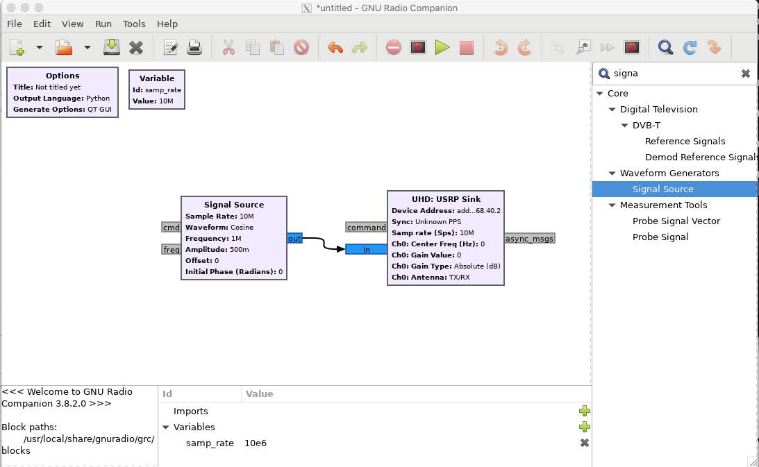

Here, the "Signal Source" generates samples for a 1 MHz cosine wave at the flowgraph sample rate, in this case 10 MHz. The samples then go into a "UHD USRP Sink". The "UHD USRP Sink" is what takes the signal samples generated in GNU radio and sends them to the USRP for transmission.
You can add blocks by clicking the magnifying glass to open a search bar and then search. Drag the block from the list into the flowgraph or double click and it will show up. To make connections, click on a blue tab and drag to another one.
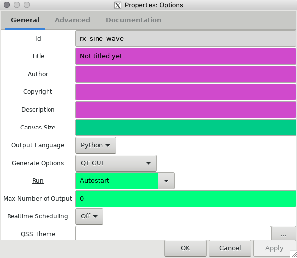
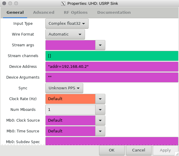
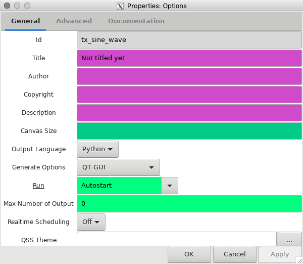
You will need to set values for samp_rate as well as parameters in each of the blocks. Double clicking on a block will bring up an editor for all parameters that a block uses. See below for the parameters used in this experiment for each block:
Figure 2: Transmitter Flowgraph Parameters 


(a) UHD USRP Sink (b) Signal Source © Options


Note that in the USRP Sink, we are setting the address to be 192.168.40.2. This is the same address we were setting up the network card interface to be able to communicate with earlier.
After all of these parameters have been entered, press the green play button. It will prompt you to save the flowgraph, you can save it in the default directory with the filename x310_tx.grc.
When the flowgraph runs, it should after some seconds open up a new GUI window with nothing on it. This is OK, it is blank simply because we used no GUI blocks. To stop it running, simply close this window.
Receiver
Start GNU Radio on node1-2:
root@node1-2:~# gnuradio-companion
We want to build a flowgraph that looks like the following:
Figure 3: Receiver Flowgraph 

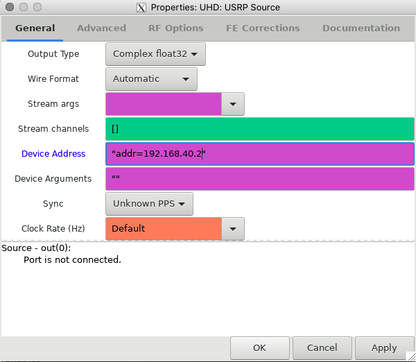
Instead of a USRP Sink, we have a USRP Source. This gives us samples received by the radio receiver at the specified sample rate of 10 MHz. We then feed these samples into a "QT GUI Frequency Sink", which will allow us to see the frequency spectrum of the signal we are receiving. We need the following parameters set up:
Figure 4: Receiver Flowgraph Parameters 
(a) UHD USRP Source (b) Options


Once everything is set up (remember to change samp_rate as well), hit run, and save as x310_rx.grc. After a little while, a small GUI window should show up like below:
Figure 5: Receiver GUI 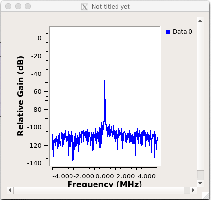

The strong peak at zero frequency is likely due to some sort of DC offset on the received signal. It is not ideal that it is there, but we can ignore it.
Running the Experiment
Now, we can finally run our experiment. To do so, simply start the two flowgraphs from GNU Radio using the green play button as before. Start x310_rx.grc on node1-2 first, and observe the same figure as Figure 5. Then, start x310_tx.grc on node1-1. If everything worked out correctly, then you should see the following:
Figure 6: Receiver GUI with transmitter operational 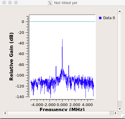

Here, you can now see two peaks at 1 MHz offset. Remember that this was the frequency we chose for the cosine wave in x310_tx.grc.
Congratulations! Everything worked. Now we can try some other things, like using a time sink instead of a frequency sink, or transmitting a different waveform. Feel free to give other things a go!
Troubleshooting
xterm Executable Not Found
Ignore it, it means nothing.
FPGA Compatibility Mismatch
You may run into the following error when running the experiment:
[INFO] [X300] X300 initialization sequence...
Error: RuntimeError: Expected FPGA compatibility number 38, but got 36:
The FPGA image on your device is not compatible with this host code build.
Download the appropriate FPGA images for this version of UHD.
Please run:

 "/usr/local/lib/uhd/utils/uhd_images_downloader.py"

Then burn a new image to the on-board flash storage of your
USRP X3xx device using the image loader utility. Use this command:

"/usr/local/bin/uhd_image_loader" --args="type=x300,addr=192.168.40.2"

For more information, refer to the UHD manual:

 http://files.ettus.com/manual/page_usrp_x3x0.html#x3x0_flash
This is basically saying that the FPGA on the USRP X310 is a different version than that expected by UHD. To fix this issue, simply follow the commands as stated:
root@node1-X:~# /usr/local/lib/uhd/utils/uhd_images_downloader.py
root@node1-X:~# /usr/local/bin/uhd_image_loader --args="type=x300,addr=192.168.40.2"
Upon running the second command, you should see the following output:
[INFO] [UHD] linux; GNU C++ version 7.5.0; Boost_106501; UHD_4.0.0.0-25-g1a34ba8a
Unit: USRP X310 (30F110A, 192.168.40.2)
FPGA Image: /usr/local/share/uhd/images/usrp_x310_fpga_HG.bit
-- Initializing FPGA loading...successful.
-- Loading HG FPGA image: 0% (0/121 sectors)
Do not do anything on the node while this is running. An incomplete FPGA imaging process will brick the USRP X310 and render it totally unusable.
When it has completed, exit the node:
root@node1-X:~# exit
Once back in the console, power cycle the node using OMF. You can now log back into the node over SSH and continue on by setting up the network interface again.
The "imaging" outlined here is a very different procedure to "imaging" the node with a .ndz file. When imaging a node with a .ndz file, we are basically overwriting the hard drive with a backup. Imaging an FPGA on a USRP (or any FPGA in general) is the process of loading a new digital circuit configuration onto the FPGA's EEPROM - a much more delicate process which is why it must complete without disturbance.
Attachments (12)
- x310_sb2_tx_flowgraph.png (107.6 KB ) - added by 5 years ago.
- x310_sb2_tx_usrp_sink.png (50.4 KB ) - added by 5 years ago.
- x310_sb2_tx_signal_source.png (33.4 KB ) - added by 5 years ago.
- x310_sb2_tx_options.png (40.8 KB ) - added by 5 years ago.
- x310_sb2_tx_options.2.png (40.8 KB ) - added by 5 years ago.
- x310_sb2_rx_options.png (41.1 KB ) - added by 5 years ago.
- x310_sb2_rx_usrp_source.png (44.6 KB ) - added by 5 years ago.
- x310_sb2_rx_flowgraph.png (116.8 KB ) - added by 5 years ago.
- x310_sb2_rx_spectrum.png (28.5 KB ) - added by 5 years ago.
- x310_sb2_rx_spectrum_tx_on.png (24.2 KB ) - added by 5 years ago.
-
x310_sb2_tx_usrp_sink.2.png
(47.3 KB
) - added by 14 months ago.
Modified configuration that contains a different value for sync field.
-
x310_sb2_rx_usrp_source.2.png
(47.5 KB
) - added by 14 months ago.
Modified configuration that contains a different value for sync field.
Download all attachments as: .zip