
Smart Intersection Situational Awareness
Smart Intersection Situational Awareness
WINLAB Summer Internship 2023
Group Members: Peter Wilmot, Heneil Patel, Eleonore Pichon
Project Objective
Combine input from multiple cameras in the orbit smart city environment to create a fused model which can be used for detection of cars and pedestrians. This project will require some knowledge of computer vision techniques. Students will work with camera feeds from both rgb and depth cameras, and will be responsible for writing code and developing procedures to synchronize and calibrate the cameras. There are several different tasks for this project:
- Calibration and fusion of multiple depth camera feeds: There are four Intel realsense cameras placed in the smart intersection environment, providing multiple views of the intersection from different angles. Because the realsense cameras are rgb-d cameras, they each provide a point cloud data stream. These point clouds can be combined to form a more complete 3d data stream of the intersection environment. This can be done simply if the positions of the cameras relative to each other in 3d space are known. Students will research and implement a routine for “calibrating” the depth camera deployment, thereby finding the positions of all of the cameras and allowing for the combination of the point cloud data.
- Image stitching of multiple top-down rgb cameras: The smart intersection includes several overlapping top-down views meant to allow for remote control of the vehicles in the environment. The video from these cameras needs to be stitched in real time to create a single video stream with the full top-down view.
- (Optional) Fusion of all views in the intersection: If both the depth camera fusion and top-down stitching projects are finished before the end of the internship, the next step is to combine both views of the intersection with any available views from vehicles driving through the intersection.
Students should get started with this project by using ROS (robot operating system) to get video streams from all of the depth cameras in the intersection. There is a realsense library for ROS, which should simplify getting all of the camera streams into one place.
Meeting time: Thursdays at Noon
Progress
Camera Calibration
- We used opencv and ArUco markers to detect points in the intersection. This allows us to find common points that are in view of multiple cameras.
- Utilizing the depth streams from the cameras, we converted these points into 3D coordinates.
- We created a server and client using python sockets to send pickle files containing the points and their labels between different nodes.
- By comparing the ids of the markers detected by each camera, we found common points and used the Kabsch algorithm to find a translation and rotation from one set of points onto the other.
- We had to convert the rotation matrix from the Kabsch algorithm to yaw pitch and roll to rotate the points.
- Using ros, we initialized each camera with Pointclouds enabled and exported the streams to one node.
- We then opened Rviz (Ros Vizualization) to view the Pointclouds.
- We used the ros static transform publisher to translate and rotate the pointclouds in relation to each camera's depth_optical_frame.
- This was inconsistent and still showed error even at its best. We decided that our transformation/visualization methods might be the issue, so we stopped using Ros for now.

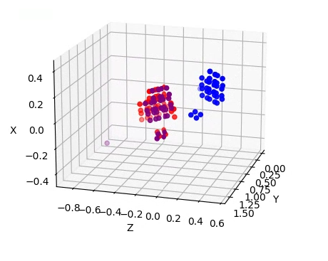
- Using opencv and matplotlib, we displayed the detected 3D points from two of the cameras, and translated the points from one of the cameras according to our Kabsch results. It is clear that our algorithm is working correctly, and this works for every pairing of cameras.


- Without ros we needed to find a way to stream the cameras to one node, and the ethersense package seemed promising. It uses python sockets to transfer live camera streams over ethernet. It required some reformatting and minor changes but the camera views are now streaming, we just need to figure out how to view/manipulate these streams on the host node.
- After viewing the ethersense data it is lacking in visibility and we are unsure how to manipulate the data, if it is even sending more than image frames.

- We didn't end up using ethersense and instead created our own script that utilized the process in the "opencv_pointcloud_viewer" and sent this data in the form of pickle files to the host node. We then modified the pointcloud viewer to view multiple pointclouds and transform the selected pointclouds.

- We believed that the poor calibration was a result of only using a set of points that were very close to each other.
- Although it seemed that the absolute error was very low, this was because the points were relatively close together.
- In reality, the relative error was very high, and this was visible when viewing the point clouds.
- Our solution to this was to add more ArUco markers.
- We also improved our ArUco marker detection script to cache the previously detected ArcUo markers, since different markers were being detected each frame. This also improved our calibration.

- The difference can be seen between the image above and below. Above the markers are continuously flashing while below the markers are constantly being recorded. This is important because we only capture the data from the most recent frame, so having all of the markers in the frame ensures the most data.

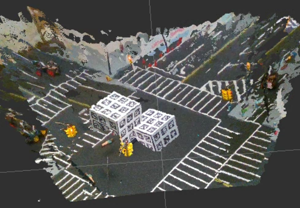
- Below is the most recent calibration between cameras 1 and 2. The error here is negligible and we consider this calibration complete. However, we have had issues with calibrating other cameras.
.gif "Best calibration of two cameras rotating")

- This gif also highlights one of the main benefits of using multiple cameras. Behind the cube on one view there is an empty section that we have no information about. By combining the camera views, we now have information about this previous blind spot.
- We starting working on sending multiple point cloud frames, but had issues rendering both the streamed, and local point clouds at the same time. It would work for a few seconds, but then the pipeline would break. We are unsure what exactly causes this, likely an issue with reading from two different files at the same time. The first image is the locally rendered frames and the second is the streamed frames.


Detection
- With our calibration looking promising, we started looking into what we would be doing with the calibrated cameras and point clouds.
- We were instructed to start working on object recognition using the Deep Learning model YOLOv8.
- We had to upgrade our python version from 3.6 to 3.9 to use this model.
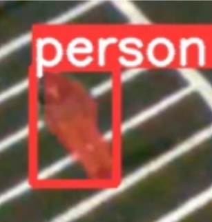
- We wrote a basic script to take the video from the camera and run the detection model on it. Below is our initial results.

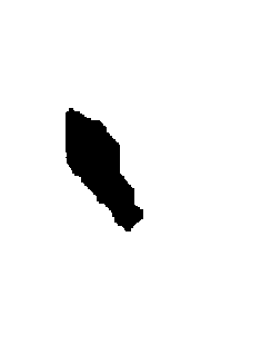
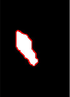
- We also ran the segmentation model which outlines the precise figures that are detected. These points can be used in the future to separate the objects in the point clouds.

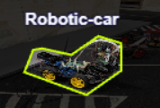
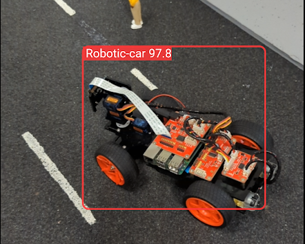
- We were requested to add to the model so that it can detect the DIY cars that other groups were building, so we took 19 images and labeled them with the shapes of the cars using Roboflow.

- We were able to train and deploy this model on the Ultralytics Hub mobile app for real-time detection, and it was very accurate, however had many false positives when no cars were in the area.

- This model was extremely slow on the phone and especially so when using the Realsense camera on the node, but it was still impressive considering only 19 images were used.

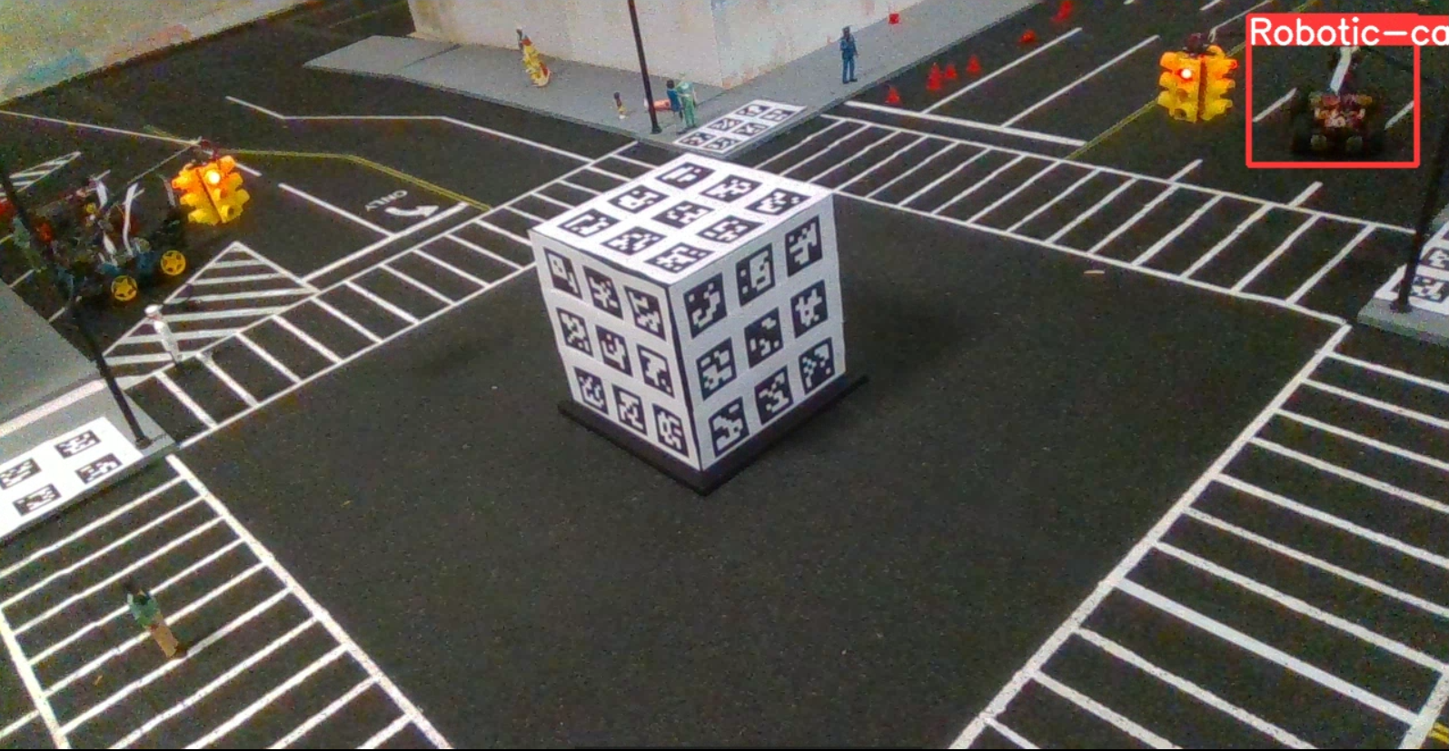
- We plan to combine our dataset with the COCO17 dataset, which YOLOv8 uses for its training so that we have a model that can detect everything we want. Then we want to start combining the detections from multiple cameras. This may include drawing multiple rectangles from the boxes created by each camera resulting in an image like the one below.

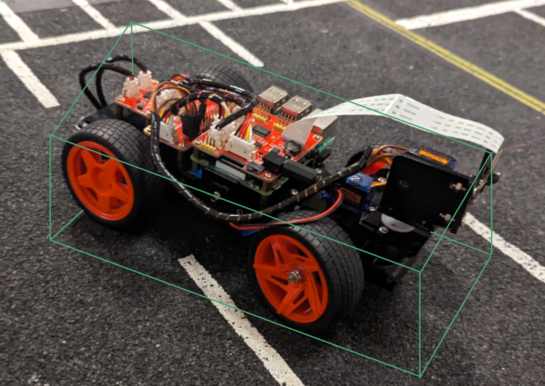
- Ideally, we will update our model to add the segmentation feature and combine the "masks" of the objects to separate the point cloud of the detected object. This would be used later to send object information to smart cars and to track the movements of these objects within the intersection.
- We successfully extracted the segmentation points from the object recognition model. Our next challenge would be to find multiple segmentations of the same object from different cameras, and to use these points to either create a bounding box or other type of mesh to separate the object from the rest of the point cloud.


Attachments (21)
-
cam1-2 better.png
(425.9 KB
) - added by 3 years ago.
Calibration when using Ros to view pointclouds
-
Calibration.png
(101.5 KB
) - added by 3 years ago.
Detected point transformation
-
1to2pointcloudviewer_V1.gif
(23.0 MB
) - added by 3 years ago.
Gif of Calibration points
-
ethersense_V3.gif
(2.7 MB
) - added by 3 years ago.
View from ethersense fixed scripts
-
12calibrationtoggle_AdobeExpress.gif
(3.6 MB
) - added by 3 years ago.
Best calibration of two cameras with one toggling view
-
12goodcalibration_AdobeExpress (1).gif
(10.3 MB
) - added by 3 years ago.
Best calibration of two cameras rotating
-
better_marker_detect_AdobeExpress.gif
(10.5 MB
) - added by 3 years ago.
Marker detection with caching
-
old_marker_detect_AdobeExpress.gif
(5.9 MB
) - added by 3 years ago.
Old detection of ArUco markers
- yolo detect.gif (2.6 MB ) - added by 3 years ago.
- yolo segment.gif (4.2 MB ) - added by 3 years ago.
- manual label.png (31.0 KB ) - added by 3 years ago.
- detected car.png (1.8 MB ) - added by 3 years ago.
- 3d car.png (3.5 MB ) - added by 3 years ago.
- high accuracy car.png (260.9 KB ) - added by 3 years ago.
- Recording 2023-06-22 134949 - Trim.mp4 (4.4 MB ) - added by 3 years ago.
- Studio_Project_V1.gif (20.2 MB ) - added by 3 years ago.
-
fewframes_-_Trim_AdobeExpress.gif
(3.0 MB
) - added by 3 years ago.
Rendering of streamed frames from different node.
-
clientstream_AdobeExpress.gif
(10.5 MB
) - added by 3 years ago.
Rendering of the constantly updating local pointcloud.
- detected person segment.png (1.3 KB ) - added by 3 years ago.
- detected person outline.png (1.6 KB ) - added by 3 years ago.
- detected person.png (134.9 KB ) - added by 3 years ago.
.gif)