
How to code and use Various Mobility Model Scripts to Emulate Mobility on ORBIT
Goal
In order to emulate mobility at stationary nodes, like ORBIT nodes, there are three different main techniques used. First one is; by changing the injected noise power between two neighbor nodes, adjusting SNR value, so, increasing and decreasing packet loss ratios. Second approach is, MAC filtering the incoming packets and dropping them by a determined ratio, so to adjust packet loss probability. The last approach is switching to different stationary nodes in a predetermined order. In other words, sending packets from the stationary nodes on the predetermined mobility path at predetermined time intervals. This approach is called Spatial Switching. In this tutorial, you will learn how to code and use different mobility models by the help of Spatial Switching approach in order to emulate mobility on ORBIT.
Architecture of Spatial Switching and Previous Works
Before going into details of different mobility models and the framework for implementing new ones, it is crucial to read and understand Mobility Emulation using Spatial Switching tutorial and the corresponding publication for figuring out the basics of spatial switching.
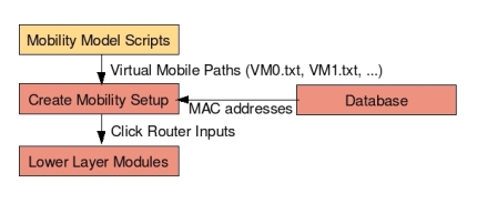
Additional to Mobility Emulation using Spatial Switching tutorial, below you can find some more brief information about Spatial Switching and the parts of Spatial Switching that this tutorial concentrates on. Since, this mobility emulation technique is implemented modularly, it is easy to understand, develop and update each step after learning modules. The module that we concentrate on this tutorial is Mobility Model Scripts, the orange box in the below hierarchy;

As seen at the above figure, the emulation process is triggered by a Mobility Model Script. Then its output files which are called Virtual Mobile (VM) Paths -sequence of ORBIT grid nodes on a mobile's path-, are fed to Create Mobility Setup script as input files. Create Mobility Setup Script fetches the used grid nodes' the MAC addresses from Database and combines them and makes them ready for the Click Router scripts.
Framework for a new Model Implementation
This part of the tutorial is about structure of the output VM*.txt files and important points should not be missed while implementing a new mobility model script.
Structure of the output VM*.txt files
The example mobility model scripts are implemented with perl scripting language. For your easiness you can implement your own model in any language you want. The important point not to be missed is, every implementation must prepare mobile nodes' movement sequence as text files on ORBIT grid when it terminates. Each Virtual Mobile (VM) node's movement sequence must be written to a separate text file, named as VM1.txt, VM2.txt and so on. Numbering of the output text files must start from 1.
At the content of the VM*.txt files, there are several lines indicating the starting time of the nodes and their coordinates at the grid. The structure of each line is as follows; the numbers at the beginning of the each line indicate the operational starting time of the nodes in seconds. One node stays active till to the next nodes starting time. The difference between each number is the node's activation duration. Next to the starting time at each line, on the right, the “node-” indicates the active node with its coordinates on the grid. For more detail, please refer to Mobility Emulation using Spatial Switching tutorial.
Since randomness is involved to the models and so to the scripts, every time you run the script you get different paths and so, VM*.txt files. If you want to resume with your previous path, save the VM*.txt files carefully.
Important Points should be Considered while Coding
Here are the significance parts of the implementation;
- One ORBIT node at any given time can only emulate one mobile device's movement. In other words, one node can not be active for two or more mobile nodes' movement at the same time. Therefore, Virtual Mobile (VM) nodes' collisions must be considered carefully during mobility implementations. (see IsUnique() function at example scripts provided at this tutorial).
- The nodes at the grid are numbered between 1 to 20. Avoid getting 0 or 21 as node coordinates. Otherwise your mobility model may stuck on the run, unexpectedly.
Usage of Existing Mobility Model Scripts
Some of the frequently used mobility models are implemented for users' easiness. Please, note that the following mobility scripts are preparing the VM*.txt files as output. After having these files, you need to follow the steps mentioned at the Mobility Emulation using Spatial Switching tutorial to run mobility emulation on ORBIT. Available mobility model scripts and their usage forms are as follows;
Random Walk with Reflection
A mobile node moves a specified time from it current position to a new location by randomly choosing a direction and speed from particular speed and direction distributions. [1] In fact this model is not bounded, but by putting destination limits, some artificial bound added to the model.
IMPORTANT point to be noted here is, this model can not be run for multiple nodes. The reason is; the direction and the duration of the mobility do not change during the movement, but determined at the beginning of the movement. Therefore, if two or more nodes collide at some time at some grid node, there is no way to change the route and recover from it. Hence, this mobility model implemented for 1 VM.
Click here to download Random Walk with Reflection Mobility Model;
Here are the parameters with example values, you can change the values according to your requirements;
$sourceXValue = 2; # Source X value
$sourceYValue = 2; # Source Y value
$walkDuration = 1000; # Walk duration in unit time in one direction. When this time elapses change direction
$speed = 100; # Average speed of the VMs
$angle = 360; # Angle randomness of the movements
$numberOfStops = 50; # Number of destinations before script terminates
Random Walk with Wrap
This mobility model is very similar to the Random Walk with Reflection. When the mobile nodes hit the boundaries they are wrapped to the other side of the simulation area from where they continue their trip. [1] In fact this model is not bounded, but by putting destination limits, some artificial bound added to the model.
IMPORTANT point to be noted here is, this model can not be run for multiple nodes. The reason is; the direction and the duration of the mobility do not change during the movement, but determined at the beginning of the movement. Therefore, if two or more nodes collide at some time at some grid node, there is no way to change the route and recover from it. Hence, this mobility model implemented for 1 VM.
Click here to download Random Walk with Wrap Mobility Model;
Here are the parameters with example values, you can change the values according to your requirements;
$sourceXValue = 2; # Source X value
$sourceYValue = 2; # Source Y value
$walkDuration = 1000; # Walk duration in unit time in one direction. When this time elapses change direction
$speed = 100; # Average speed of the VMs
$angle = 360; # Angle randomness of the movements
$randomnessInterval = 2; # Maximum distance that a node can jump at an iteration
$numberOfStops = 50; # Number of destinations before script terminates
Random Distance
This model is slightly similar to the Random Walk with Wrap model. The mobile nodes move until they reach a randomly chosen distance from the simulation boundary. The difference is this model is bounded by its nature. [1] The model may terminate in two different ways; running time of the model may elapse or all destinations may be visited.
IMPORTANT point to be noted here is, this model can not be run for multiple nodes. The reason is; the direction and the duration of the mobility do not change during the movement, but determined at the beginning of the movement. Therefore, if two or more nodes collide at some time at some grid node, there is no way to change the route and recover from it. Hence, this mobility model implemented for 1 VM.
Click here to download Random Distance Mobility Model;
Here are the parameters with example values, you can change the values according to your requirements;
$sourceXValue = 2; # Source X value
$sourceYValue = 2; # Source Y value
$walkDuration = 1000; # Walk duration in unit time in one direction. When this time elapses change direction
$speed = 100; # Average speed of the VMs
$angle = 360; # Angle randomness of the movements
$randomnessInterval = 2; # Maximum distance that a node can jump at an iteration
$numberOfStops = 50; # Number of destinations before script terminates
$runningTime = 100; # Running time bound for the script. when this equals to 0, program terminates
Reference Point
This mobility model forms the basis of Random Waypoint and Weighted Waypoint models and can be run for several VM's.
Click here to download Reference Point Mobility Model;
Here are the parameters with example values, assuming 3 Virtual Mobile (VM) Nodes are in the system. You can change the values according to your requirements;
@sourceXValue = (19, 1, 4); # Source X values of all 3 VMs.
@sourceYValue = (15, 4, 12); # Source Y values of all 3 VMs.
		             # e.g.: First node is at (19,15)
@destinationXValue = ([2, 12, 19], [2, 3, 7], [3, 0, 0]); #Checkpoints' X values for 3 mobile nodes
@destinationYValue = ([3, 20, 20], [3, 1, 17], [4, 0, 20]); #Checkpoints' Y values for 3 mobile nodes
#Checkpoints for VM1 is (2,3), (12,20), (19,20)
#Checkpoints for VM2 is (2,3), (3,1), (7,17)
#...
$numberOfDestinations = scalar(@destinationXValue); # Number of checkpoints to be visited
$maxIntervalTime = 100; # Maximum waiting time at a node
$minIntervalTime = 10; # Minumum waiting time at a node
@accelerationRandomness = ([25, -5, -2],
			   [12, -4, -4],
			   [32, -12, 3]); # Acceleration values between checkpoints, e.g.: Between VM1 source and 1st checkpoint point acceleration is 25, then -5, last, -2 and same for other VMs.
$randomnessInterval = 2; # Maximum distance that a node can jump at an iteration
$mobileNumber = 3; # Number of VMs.
Random Waypoint
Each mobile node individually chooses a random destination within the simulated network boundary, and also determines a motion speed randomly chosen between a minimum and maximum limit. Based on this, it movers toward its destination at its determined velocity. Once the destination has been reached, each node stops for a randomly chosen time interval. After that pause time, it then repeats the process by choosing another random destination and a random speed. [1]
Click here to download Random Waypoint Mobility Model;
Here are the parameters with example values, assuming 3 Virtual Mobile (VM) Nodes are in the system. You can change the values according to your requirements;
@sourceXValue = (1, 1, 4); # Source X values of all 3 VMs.
@sourceYValue = (1, 4, 12); # Source Y values of all 3 VMs.
			    # e.g.: First node is at (1,1)
$numberOfDestinations = 3; # The number of destinations that you want VM to travel
$maxIntervalTime = 100; # Maximum waiting time at a node
$minIntervalTime = 10; # Minimum waiting time at a node
@accelerationRandomness = ([25, -5, -2],
			   [12, -4, -4],
			   [32, -12, 3]); # Acceleration values between checkpoints, e.g.: Between VM1 source and 1st checkpoint point acceleration is 25, then -5, last, -2 and same for other VMs.
$randomnessInterval = 1; # Maximum distance that a node can jump at an iteration
Weighted Waypoint
This mobility model is pretty similar to the Random Waypoint model. The difference is, it is assumed that the destination points are not randomly chosen. Rather, there are sequence of checkpoints that the mobile nodes follow. Between these checkpoints some predetermined randomness added so that the paths between the checkpoints are not same. [2]
Click here to download Weighted Waypoint Mobility Model;
Here are the parameters with example values, assuming 3 Virtual Mobile (VM) Nodes are in the system. You can change the values according to your requirements;
@sourceXValue = (19, 1, 4); # Source X values of all 3 VMs.
@sourceYValue = (15, 4, 12); # Source Y values of all 3 VMs.
			     # e.g.: First node is at (19,15)
@destinationXValue = ([2, 12, 19], [2, 3, 7], [3, 0, 0]); #Checkpoints' X values for 3 mobile nodes
@destinationYValue = ([3, 20, 20], [3, 1, 17], [4, 0, 20]); #Checkpoints' Y values for 3 mobile nodes
#Checkpoints for VM1 is (2,3), (12,20), (19,20)
#Checkpoints for VM2 is (2,3), (3,1), (7,17)
#...
$numberOfDestinations = scalar(@destinationXValue); # Number of checkpoints to be visited
$maxIntervalTime = 100; # Maximum waiting time at a node
$minIntervalTime = 10; # Minumum waiting time at a node
@accelerationRandomness = ([25, -5, -2],
			   [12, -4, -4],
			   [32, -12, 3]); # Acceleration values between checkpoints, e.g.: Between VM1 source and 1st checkpoint point acceleration is 25, then -5, last, -2 and same for other VMs.
$randomnessInterval = 2; # Maximum distance that a node can jump at an iteration
$mobileNumber = 3; # Number of VMs.
References
[1] Harri, J., Filali, F., Bonnet, C., A framework for Mobility Models Generation and its Application to Inter-Vehicular Networks, Wireless Networks, Communications and Mobile Computing, 2005 International Conference on, Publication Date: 13-16 June 2005. Volume: 1, On page(s): 42- 47 vol.1
[2] Wei-jen Hsu, Kashyap Merchant, Haw-wei Shu, Chih-hsin Hsu, Ahmed Helmy, ACM SIGMOBILE Mobile Computing and Communications Review, Volume 9, Issue 1 (January 2005), COLUMN: Special feature on MOBICOM 2004 posters, Pages: 59 - 63, Year of Publication: 2005, ISSN:1559-1662
Attachments (7)
- RandomDistance.pl (5.2 KB ) - added by 18 years ago.
- RandomWalkwithReflection.pl (6.0 KB ) - added by 18 years ago.
- RandomWaypointMoveManyDestinationsMultiNodeIsUniqueAdded.pl (12.0 KB ) - added by 18 years ago.
- ReferencePointMoveManyDestinationsMultiNodeIsUniqueAdded.pl (12.5 KB ) - added by 18 years ago.
- WeightedWaypointMoveManyDestinationsMultiNodeIsUniqueAdded.pl (11.8 KB ) - added by 18 years ago.
- RandomWalkwithWrap.pl (4.8 KB ) - added by 18 years ago.
- SSArchitectureBasic.jpg (26.1 KB ) - added by 18 years ago.
Download all attachments as: .zip