
| Version 2 (modified by , 19 years ago) ( diff ) |
|---|
Chassis Manager (CM) Hardware Description
A simple low cost embedded processor with the following characteristics is needed for the ORBIT Chassis Manager:
- Multiple programmable digital I/O lines
- Low EMI
- Small size
- Low power
- Rapid development cycle
- C-language program development and debugging
- Low cost

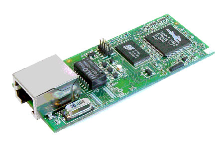
The RCM3700 Rabbit Core meets all these requirements as shown below:
- Small Footprint: 2.95” x 1.2”; 100ma @ 5v
- 512K Flash, 512K SRAM
- 10Base-T Ethernet w/RJ-45 connector
- 33 digital I/O ports, 4 serial ports
- 22.1 Mhz Z-80 based Processor
- Complete “Dynamic C” development system package
- Royalty-free TCP/IP libraries
- $49, qty 100
The software development system for the RCM3700 is completely integrated within the “Dynamic C” tool set. Dynamic C contains a C compiler, editor, loader, and source/assembly debugger specifically tailored for Rabbit microprocessor-based products. It includes hundreds of functions in source-code libraries. (ex. floating-point arithmetic and transcendental functions, serial communication drivers, analog and digital I/O drivers, I2C, SPI, GPS, encryption, file systems, etc.) TCP/IP libraries include HTTP, POP2, TFTP, FTP, SMTP, DHCP, Socket-Level UDP/TCP, and ICMP. Also, the preemptive operating system called microC/OS-II is fully supported.
Note: The Dynamic C TCP/IP library functions are slightly different from Unix syntax, and are not directly portable to non-Rabbit platforms.
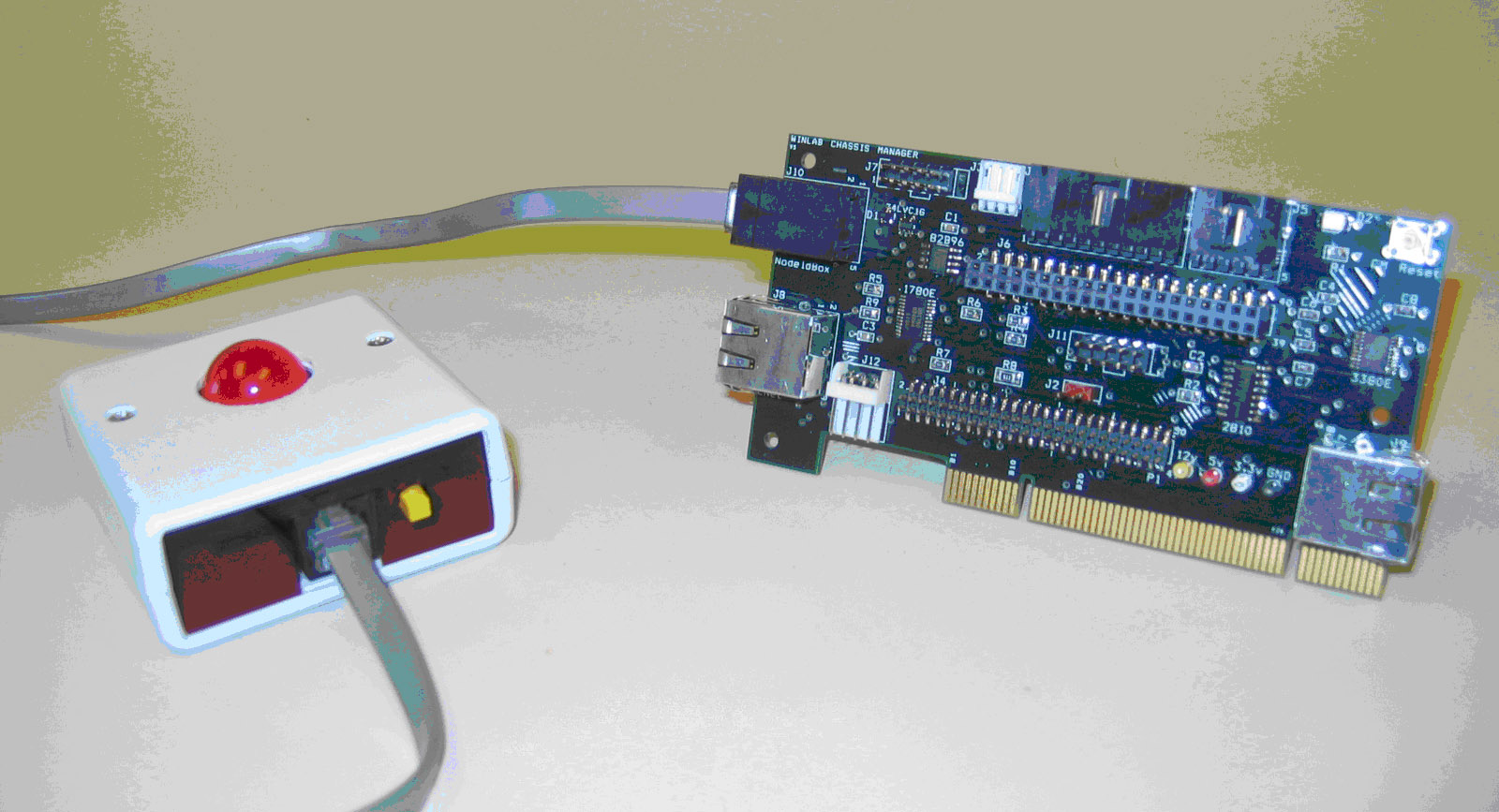
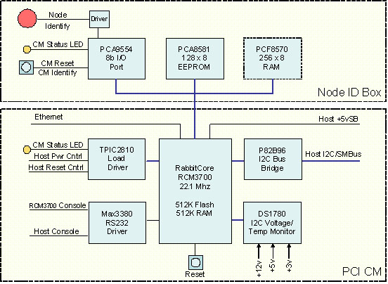
The CM has two components: a CM PCI card that connects directly to the host, and a NodeIDBox that permanently mounts on a fixture at each grid position. The CM block diagram is shown in Figure 5.
 Two serial ports on the RCM3700 provide the RCM3700 console and the host console interface. Another port on the RCM3700 provides I2C clock and data. The CM design is primarily based upon I2C bus components. The I2C (Inter-Integrated Circuit) Bus is a low-cost two-wire, low to medium speed communication bus designed for chip-to-chip communication. I2C was developed by Philips Semiconductor in the early 1980’s, and is commonly found in computers built today. The I2C components used in the CM are summarized in Table 2 below:
| Location | Part | Function |
| CM-PCI | DS1780 | Voltage/Temp monitor |
| CM-PCI | TPIC2810 | 8-bit high-current driver |
| CM-PCI | P82B96 | I2C/SMBus bridge to host I2C/SMBus |
| !NodeIDBox | PCA9554 | 8-bit I/O TTL Port |
| NodeIdBox | PCA8581 | EEPROM 128x8b |
| NodeIdBox | PCF8570 | 256x8 RAM (future use) |
Table 2 CM I2C Components
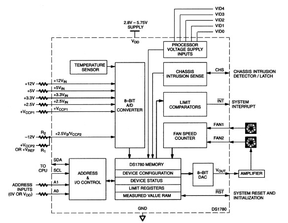
DS1780
Voltage and temperature monitoring is achieved using the I2C-based Dallas Semiconductor DS-1780. This device is a 24-pin direct-to-digital chassis system monitor. It is capable of monitoring ambient temperature, six power supply voltages, and the speed of two fans. Fan speed can also be controlled from this device using an internal 8-bit ADC. See the DS-1780 Block Diagram in Figure 6.

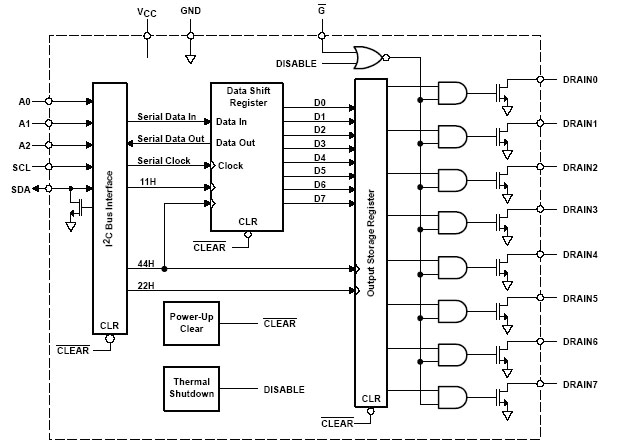
TPIC2810
The microprocessor used in the CM, the RCM3700, has a capability of sourcing or sinking only 6.8ma maximum per pin. The TPIC2810 is used to drive higher current devices, e.g. LEDs, and the unknown current requirements of, for example, the Power and Reset signals of an unspecified host. Each output pin on the TPIC2810 can drive 100ma continuous / 210ma maximum using open-drain DMOS transistor outputs as shown in Figure 7.

P82B96
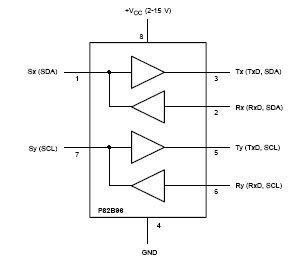
The P82B96 is used to create a non-latching bi-directional logic interface between a normal I2C bus and a wide range of I2C or SMBus configurations at different logic voltage levels. It is used in the CM to bridge between the CM I2C bus and the Radio Node (or other host) I2C or SMBus. The block diagram of the P82B96 is shown in Figure 8. A small circuit disables the P82B96 if either CM or Host power I2C power is not available, thus isolating the unpowered bus.

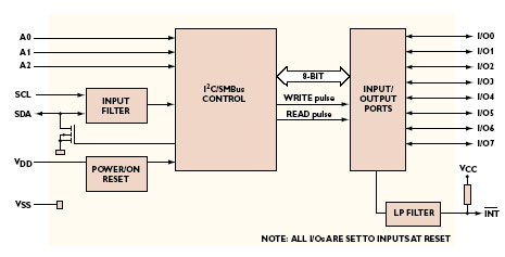
PCA9554
In the NodeId box, the PCA9554 is used for a general purpose 8-bit GPIO expansion on the I2C bus. Each bit can be configured for input or output, and the polarity of each bit can software configured. The drive output on each bit is 25ma maximum, and 100ma over all 8 bits. This device is used to read the N.O. momentary contact switch used to reset the CM, or to send an Identify Message back to the CMC. (The function is dependent upon the duration the switch is held). The PCA9554 is also used to drive the large red LED used to identify the Node. The red LED is driven through a off-chip NPN transistor to allow the LED to operate on a higher voltage and current than allowed by the PCA9554. A small CM status LED is also driven directly by this device. Figure 9 has the block diagram for the PCA9554.

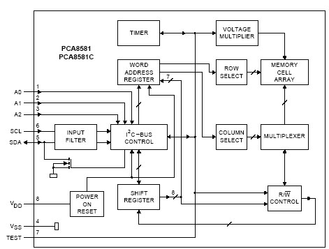
PCA8581
One of the primary functions of the Node ID box is to store the fixed grid coordinate for the node location in the grid. The grid coordinate is used for location information as well as defining the static IP address of the CM, and Host node. The PCA8581 is a 128 x 8b EEPROM with typical word-addressable auto-increment memory access. It is important to note that this device uses all three address pins to define the I2C hardware address, unlike a similar part, the 24LC01, which ignores the three address pins. Having active address pins permits specific placement of this device in the I2C address space to avoid conflict with similar devices in the host system that are sharing the I2C bus over the P82B96 bridge. The PCA8581 is shown in Figure 10 below.

PCF8570
The 256 x 8 PCF8570 I2C RAM device is included in the CM design for future use, and is not used on the initial CM boards. Its design consideration addresses inter-processor communication between the CM and the Host node.
I2C Address Map
The address assignments of the CM I2C components were selected to avoid address collision with the same class of device on a host system. While this can not be guaranteed for all host systems, those hosts that are likely to be connected to a CM were considered.
The I2C address hard-wired for A2, A1, and A0 on a device represents the least significant 3 bits of a 7 bit I2C address field. The most significant 4 address bits are fixed within each device, and represent the “class” of device. I2C addresses are usually referenced in hexadecimal, but sometimes they are shifted right one bit to have a range of 00…7F. In this text, the right-shifted address is used, and the CM Schematics contain both shifted and non-shifted address notations.
Table 3 below shows the I2C address assignments for three hosts (Tyan, VIA, and Gigabyte) along with assignments used in the CM and Node Id components.
Table 3 I2C Address Space (Address Order)
| H/W binary Addr* | H/W Addr | S/W Addr | Host | I2C Device | |
| 0x08 | Tyan | unknown | |||
| 0x0C | Tyan | unknown | |||
| 0100 0110 | 0x46 | 0x23 | NodeID | PCA9554 (8b I/O port) | |
| 0x29 | Tyan | sensor | |||
| 0101 1010 | 0x5A | 0x2D | CM | DS1780E (temp/volt monitor) | |
| 0x2D | Gigabyte | W83791D | |||
| 0x30 | VIA | EPROM shadow | |||
| 0x44 | Tyan | sensor | |||
| 0x48 | Tyan | sensor | |||
| 0x49 | Tyan | sensor | |||
| 0x50 | VIA/Gigabyte | EEPROM | |||
| 0x51 | Tyan | EEPROM | |||
| 1010 0110 | 0xA6 | 0x53 | NodeID | EEPROM | |
| 1010 1000 | 0xA8 | 0x54 | NodeID | RAM | |
| 0x55 | Tyan | EEPROM | |||
| 1100 1000 | 0xC8 | 0x64 | CM | TPIC2810 (high current driver) | |
| 0x69 | Tyan/VIA | Clock |
- A2, A1, A0 highlighted with larger font
The physical form-factor for the Chassis Manager is a 2U PCI card measuring approximately 4.75 x 2.5 in. The Node ID box is on a board measuring approximately 2.25 x 1.75 in. Appropriate sockets permit the RCM3700 module to plug directly into the PCI card or optionally through a 10 pin ribbon cable for remote mounting.

Attachments (10)
-
CM-NodeID.jpg
(303.6 KB
) - added by 19 years ago.
NodeID Box and Chassis Manager Photo
-
PCA8581.jpg
(56.1 KB
) - added by 19 years ago.
PCA8581 Block Diagram
-
PCA9554.jpg
(38.5 KB
) - added by 19 years ago.
PCA9554 Block Diagram
-
P82B96.jpg
(28.5 KB
) - added by 19 years ago.
P82B96 Block Diagram
-
P82B96.2.jpg
(28.5 KB
) - added by 19 years ago.
P82B96 Block Diagram
-
P82B96.3.jpg
(28.5 KB
) - added by 19 years ago.
P82B96 Block Diagram
-
TPIC2810.jpg
(78.2 KB
) - added by 19 years ago.
TPIC2810 Block Diagram
-
DS1780.jpg
(76.0 KB
) - added by 19 years ago.
DS1780 Functional Block Diagram
-
CMBLockDiagram.jpg
(112.4 KB
) - added by 19 years ago.
CM & NodeID Block Diagram
-
RCM3700.jpg
(33.4 KB
) - added by 19 years ago.
Rabbit Semiconductor RCM 3700
Download all attachments as: .zip