
| Version 18 (modified by , 14 years ago) ( diff ) |
|---|
Multiple Controllers (And making them cooperate).
This page documents the process of designing a multi-controller OpenFlow architecture where the controllers actively collaborate to emulate a network stack for experiments.
This "logging" method is based on a relatively effective method developed during a GSoC 2012 project.
Quick Links.
Overview
Logistics
Subpages - extra notes related to this page
Logs - records of work
Overview.
The basic architecture for an OpenFlow network is a client - server (switch - controller) model involving a single controller and one or more switches. Networks can host multiple controllers. FlowVisor virtualizes a single network into slices so that it can be shared amongst various controllers, and the newest OpenFlow standard (v1.3.0) defines equal, master and slave controllers to coexist as part of a redundancy scheme in what would be a single slice. A multi-controller scheme that isn't really explored yet is one where each controller has a different function, and cooperate.
Cooperation is a fairly complex task, for several reasons:
- There must be a communication scheme so that the controllers can cooperate
- A single protocol suite can be divided amongst controllers in various ways
- The information being communicated between controllers changes with protocol suite and division of tasks
Developing a general solution to this problem is difficult, so focus will be narrowed down to a more specific task of producing a cooperative multi-controller framework for running a topology configuration service split into a global and local component, and an experimental routing protocol with ID resolution.
Logistics
Work Setup
The Mininet SDN prototyping tool will be used for testing and debugging implementations. The implementation will be based on modified versions of OpenFlow Hub's Floodlight controller.
Proof-of-concept experiments for evaluating the architecture will be run on ORBIT sandboxes.
Timeline
An approximate 3.5 months (14 weeks) is allotted for design, implementation, and evaluation. the ideal split of time is the following:
- 3-5 weeks: architecture layout, topology control, context framework
- 3-4 weeks (end of: week 6-9): integrating routing/resolution
- 3-4 weeks (end of: week 9-13): evaluation
- remainder (end of: week 14): documentation
This schedule is a general outline and is used as a guideline; the actual work-flow will inevitably change.
Subpages
- A Thought Exercise: A "prologue" (ASCII text) page on thinking about multi-controller architecture design to get back up to speed after a hiatus.
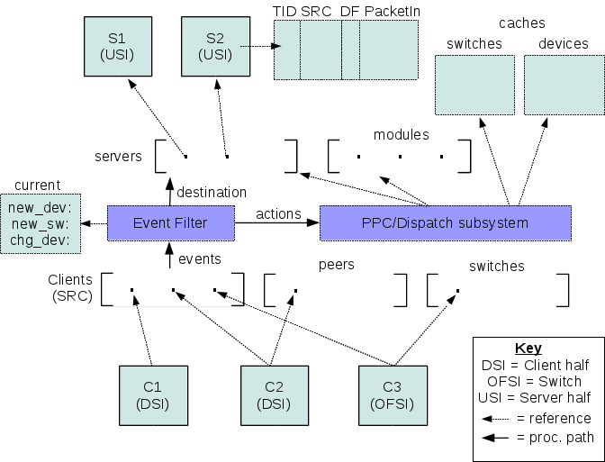
- Floodlight Internals: A summary of Floodlight internals.
Logging.
(9/5):
keywords: hierarchy, collaboration.
We are set on having a weekly meeting, starting with this one.
The consensus is that a general architecture is beyond the scope of what's possible within the available timespan. The design is simplified to a narrower case:
- controllable topology (mobility as a change in topology). A global controller with a view of the network initially configures the topology. Lower (local) controllers can detect topology change and either update the global view or handle it themselves.
- controller per service and switch
- hierarchical relation between controllers. with less active protocols higher up
- information distribution mechanism between controllers, namely service location (topology). Certain controllers may add context to port, depending on what is attached to them. The topology controller must be able to convey the location of the service to that controller. Possibly an request/reply/subscription based scheme, the subscription being useful for events (topology change).
The course of action now is to look for the following:
- Basic topology control
- Test case of mobility/handoff/flow switching (OpenRoads)
- Mechanisms that can be used to exchange service/event information
(9/7):
Added a good amount of content to Floodlight Internals.
We need to define inter-controller communication. At the basic level controllers can communicate by passing OpenFlow messages amongst themselves. This is like a not-so-transparent, upside-down version of FlowVisor.
(9/9):
The primary steps of concern seem to be the following:
- create a controller that can connect to other controllers
- pass messages between them (get one to send something to other)
- intercept and use messages (get recipient to act on message)
- make this symmetric (for request/reply/update)
somewhere along the way, we need to devise a service type message/servicetype codes that can be meaningful. For now it is probably a good sanity test to get two controllers to connect to each other, akin to what FlowVisor does.
The easiest approach may be to create a module that opens up its own connection, exporting a "switch service" that handshakes with a remote controller.
(9/10):
Beginning of creating a basis for controllers that can be connected together. Tentatively calling the controllers that are going to be part of the hierarchy "units", as in, "units of control".
This involved taking OFChannelHandler and creating something similar to it, for connections from (down-links to) other controllers. At first represented connections from units as their own implementations, then figured this was problematic if the packets from the controllers are to be handled by the modules. This means it makes sense to represent the connections from other controllers as OFSwitchImpls.
Two new mock-OFProtocol types were created for inter-unit messaging.
- OFUnitServiceRequest: request for list of services from unit
- OFUnitServiceReply: relevant service information
The service reply will probably communicate a service type (topology, network storage, etc.) and a location to find it, such as port on a datapath where a NAS is located (if network storage). This is basically a way for the network to advertise location of services to topology-aware elements, as opposed to a server attached to a network doing the adverts for hosts.
(9/11)
Some work was done to develop a general architecture of a single controller, tentatively named a "Unit". A unit can handle both switch connections as well as controller connections. Controller connections come in two flavors:
- upstream - outgoing connects to a remote one, used to pass a message to higher tiers
- downstream - incoming connections from a remote one, used to return a result to the lower tiers after processing
Incoming connections are made to a "known" port. Two controllers connected to each-other via both are adjacent.
End of week1 :Back to Logs.
(9/12)
Several points were discussed.
- Same versus different channels for switches and controllers. Same channels for both implies a need for a strictly defined protocol between controllers, and a more sophisticated upstream message handler for the channel. Different channels allows the system to be more modular, and removes the need to develop the "smart" handler that may become cumbersome to debug and develop overall.
- Vertical versus horizontal inter-controller channels. Vertical channels are connections between controllers in different layers of the hierarchy, whereas horizontal channels are between those in the same layer. Horizontal channels may contain both OpenFlow control and derived messages. Vertical messages may not conform to OpenFlow, with the exception of the vertical channel between the first level controllers and switches (the traditional OF channel).
- Nature of non-conforming messages. The Vertical messages are "domain-specific", that is, only conform to rules that are agreed upon between adjacent layers. Therefore, some translation must occur if a message is to pass across several layers. Alternately, one message type may be interpreted differently across different tiers. An Example is one layer using a VLAN tag as a normal tag, and another, a session ID.
- Interdomain handoffs. The network may be a mix of IP and non-IP networks, governed by controllers not necessarily able to communicate - each should be able to operate in their local scope, facilitating the translation of outgoing messages so that it may be handled properly by the IP portions of the internetwork.
- Use case. A small setup of three switches, two hosts (one moving), and two tiers of controllers. The first tier may be a simple forwarding unit, and the second dictates a higher (protocol) layer logic - to keep it simple, authentication. The logical layout between the two tiers changes behaviors of the tiers:
- Tier two connects to just one tier one controller: the connection point must communicate the higher-tier's commands to others in its tier.
- Tier two connects to all tier one controllers: tier two in this case is a global 'overseer' that can actively coordinate, in this case, a handoff where permitted.
(9/13)
A second channel handler was added for inter-controller communication. This involves an addition of:
- a slightly modified ChannelPipelineFactory for the new channel pipeline (the logical stack of handlers that a message received on the channel will be processed by)
- a new ChannelHandler for the socket,
UnitChannelHandler, to the controller class - a new server-side channel bootstrapping object for this port (6644, "controllerPort") to the controller class
This page was used as a reference.
End of week2 :Back to Logs.
(9/20)
A topology file/parser were added. The file is a .json list of upstream and peer controller units (nickname:host:port triplet). This list is used to instantiate client-side connections to the neighbors.
The essential difference (as of not) between an upstream and peer unit are whether the client connection goes one way or both. Several ways to identify the origin of the message comes to mind:
- keep the original lists of neighbors, and find relation by lookup per message
- identify based on which message handler object receives message. The object:
- is identified as down, up, or peer (relation)
- manages outgoing connections to upstream or peer
- raw classification:
- if received on 6644 and no client connection to originator exists, it is from downstream
- if received on 6644 and a client connection to originator exists, it is from a peer
- if received on a high-number port and originator does not connect to 6644, it is from upstream
(9/21)
Realizing that the lack of understanding of the Netty libraries was becoming a severe hindrance, we inspect a few documents to get up-to-speed:
- Netty Channel handlers: http://www.znetdevelopment.com/blogs/2009/04/21/netty-using-handlers/
- Official Netty getting-started docs: http://docs.jboss.org/netty/3.1/guide/html/start.html
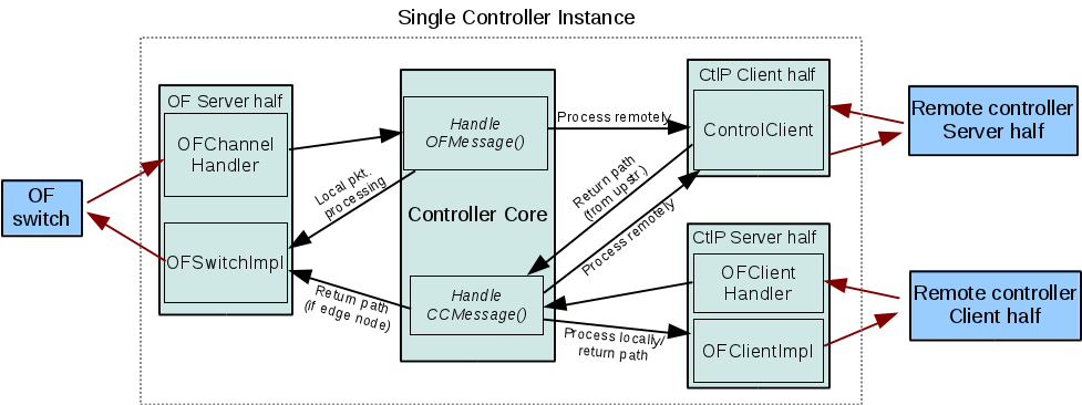
With the new resources at hand, we re-document the modifications done to the main Floodlight event handler (Controller.java) in order to intercept and respond to messages from both switches and controller units.
- The "server-side" channels. A control unit expects two types of incoming connections, 1) from switches, and 2) from other units (peer and downstream). These two are identified by default TCP port values of 6633 and 6644, respectively. The switch channel is handles using OFChannelHandler, which implements the classic OpenFlow handshake. The unit channel, which we add as the UnitChannelHandler to our Controller.java derivative class (UnitController.java), deals with the inter-unit handshake, which uses a modified version of OpenFlow. Both are initialized and added to the same ChannelGroup when the UnitController run() method is called.
- client-side channels. A controller unit with upstream or peer units will connect to other units as clients. Each client connection is handled by a UnitConnector, which attempts to connect to each remote socket specified in a topology file located, by default, under resources/ . Each entry describing a unit has the following form:
        {
    	    "name":"unit_name",
	    "host":"localhost",
	    "port": 6644
	}
This can of course be easily changed, along with its parser (UnitConfigUtil.java) and structure holding the information for each entry (UnitPair.java). This file specifies peer and upstream units in separate lists, in order to facilitate the differentiation between the two kinds of server units. We define a unit that accepts connection to be a server unit, and ones connecting, client units. A separate channel handler is supplied for this connections.
However, it appears that all three channels use similar-enough channel pipelines, whose only differences lie in which handler is being used; therefore some work to be done in the future include a consolidation of the three PipelineFactories.
End of week3 :Back to Logs.
Attachments (2)
- module_arch.png (85.4 KB ) - added by 14 years ago.
- controller_arch_rev-3.png (62.4 KB ) - added by 13 years ago.
Download all attachments as: .zip