
| Version 13 (modified by , 13 years ago) ( diff ) |
|---|
Table of Contents
Installing the CM3
Connections to the CM3
The CM3 card has a few external connections. The power connector (on board revision 4) uses a Tyco Electronics 2 pin surface mount header, the mating side to this header is here. Using vampire clips connect the positive power cable to the standby voltage from the node power supply (PS), which is typically the purple cable, or pin 9 on the 20(+4) pin power power connector. The ground wire can be connected to any of the PS ground cables.
There are two cables that should come out of the J6 header. The first cable is the 'power switch' cable (two wires) and should be plugged between the mother board (MB) power button pins (ually found on the 'front panel' header) and pins 1 & 2 on the J6 header. This cable replaces the need for a physical power switch. Similarly the 'reset switch' cable runs between pins 3 & 4 on the J6 header and the reset switch pins on the same 'front panel' header on the MB.
Using the CM3
Turning the CM3 on
Attachments (1)
-
manualIP.png
(118.4 KB
) - added by 11 years ago.
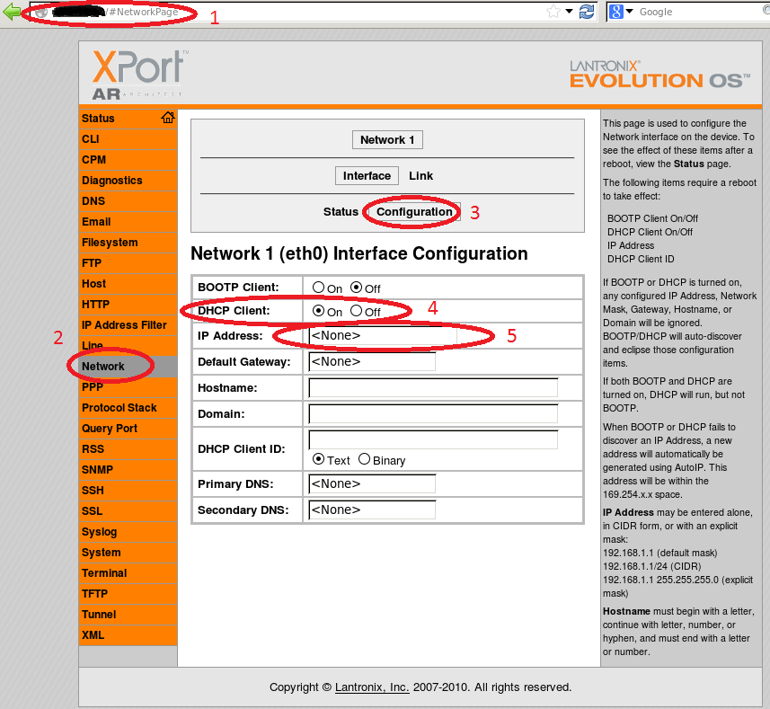
Manually Entering an IP
Download all attachments as: .zip