
Installing the CM3
Table of Contents
Connections to the CM3
The CM3 card has a few external connections. The power connector (on board revision 4) uses a Tyco Electronics 2 pin surface mount header, the mating side to this header is here. Using vampire clips connect the positive power cable to the standby voltage from the node power supply (PS), which is typically the purple cable, or pin 9 on the 20(+4) pin power power connector. The ground wire can be connected to any of the PS ground cables.
There are two cables that should come out of the J6 header. The first cable is the 'power switch' cable (two wires) and should be plugged between the mother board (MB) power button pins (usually found on the 'front panel' header) and pins 1 & 2 on the J6 header. This cable replaces the need for a physical power switch. Similarly the 'reset switch' cable runs between pins 3 & 4 on the J6 header and the reset switch pins on the same 'front panel' header on the MB.
The serial header is used to connect to the serial port on the mother board, the J4 header is another way of accessing the serial lines and uses a standard 2x5 100mil pin spacing. In the present configuration the serial cable should be a straight cable, and not a crossover (or null modem). If you wish to use a null model cable the resistors R17 and R18 must be populated, and R15 and R16 removed. The last connection that needs to be made is the power monitoring cable, which is the floppy power cable from the PS. This feeds the voltage that the CM will monitor to determine the state of the node.
Turning the CM3 on
The Lantronix Xport AR does not refresh its IP address when an ethernet cable is plugged in to is it important the that MAC address of the device already be in DHCP with the appropriate address, and that the ethernet cable be already plugged in when the device is powered on. If it is not in DHCP and plugged in to the network it will default to some unknown IP address, and will not change until reset or power cycled.
When the CM3 turns on the software will start sending UDP packets to the CMC and waiting for responses as well as monitoring the hardware status of the node. This will only happen after the Xport AR has gone through it's own boot sequence, which includes getting its IP address from the DHCP sever and booting into the custom code loaded with the CM3 image.
Using the CM3
The CM3 board, once properly plugged in and powered up will find an IP address and then load the custom software written automatically. Once the node has and IP and is powered up it should start communicating with the CMC right away. For details on the way the software works please refer to the Software Description or look at the code repository in the SVN. The UDP commands are described in more detail in the software description.
UDP
UDP commands are no longer being used as over firmware version 4.0
HTTP commands
These are the commands that can be accessed through HTTP. They all return XML pages with the success or failure of the command
| /<command> | |
| /HardOff | Hard power off command |
| /SoftOff | Soft power off command |
| /Reset | Resets the node |
| /PowerOn | Turns node on |
| /LantronixReset | Resets lantronix device (CM) |
| /Status | Returns the power state of the node |
These commands are entered after the cm address, i.e.
http://10.1.x.x/Reset
Format for the XML return pages is as follows.
Success
<<command>> OK </<command>> e.g.
<Reset>OK<Reset>
Failure
<error><command></error> e.g.
<error>Reset</error>
Status
<power>on/off</power>
Command line interface (CLI) access
Base on telnet to port 8023 (also used for Lantronix access). You can find more about implemented commands with "?" e.g.:
telnet 10.1.224.1 8023
Trying 10.1.224.1...
Connected to cons1-1.outdoor.orbit-lab.org.
Escape character is '^]'.
>ena
(enable)#cm
(cm)#?
clrscrn                                 exit
power off <hard | soft>                 power on
reset cm                                reset node
show cm                                 show history
show node                               write
Command line commands
Node related commands power on Power the node on power off hard Power the node off power off soft Issue shutdown through the console interface reset node Reset the node show node Show operating condition of node CM related commands reset cm Reset CM software show cm Show MAC, IP, and software version of CM CLI related commands show history Display previous commands entered write clrscrn Clears the screen exit Exit the CM command line mode
(cm)#show cm
Code Version: 3.1.0
MAC address:  00:20:4a:94:e3:64
IP address:   10.1.224.1
(cm)#show node
Node state:         On
Registered:       TRUE
System Temperature: 22
12V Reading:        12.000
5V Reading:         4.992
3V Reading:         3.302
Node Type:          Outdoor node
Coordinates:        [0,1]
(cm)#
Serial Console over Telnet tunnel
Telnet to IP address of CM (eg. for node1-1, do telnet cons1-1 from the testbed's console) and you will get access to serial console of the node. This will allow you to perform basic command line level repair of the node to regain SSH connectivity. The default serial settings for the serial-to-telnet tunnel are:
| Baud | 115200 |
| Parity | None |
| Data Bits | 8 |
| Stop Bits | 1 |
| Flow Control | None |
Custom Phone control firmware
There is a slightly altered version of the standard firmware designed for controlling a phone though the 3 most common buttons: power, up, and down. All the existing commands from the standard firmware still exist, so depending on the physical connections enacting the 'reset node' command may activate the 'down button' command because they access the same control pins. For this reason, for this firmware it is encuraged to only use the button ½/3 commands and nothing else.
HTTP commands
| Http address | function description |
| /1l | 5 second 'button press on button 1 |
| /2l | same as above for button 2 |
| /3l | same as above for button 3 |
| /1s | half second button press for button 1 |
| /2s | same as above for button 2 |
| /3s | same as above for button 3 |
UDP
no UDP support for this
CLI
Trying 10.1.224.61...
Connected to 10.1.224.61.
Escape character is '^]'.
>enable
(enable)#phone
(phone)#?
button <1 | 2 | 3> <long | short>       clrscrn
exit                                    show history
write
you must enter the command as such
button 1 short
Connections
Right now the connections are as such
| button | connection |
| 1 | Power |
| 2 | up |
| 3 | down |
Manually Entering an IP
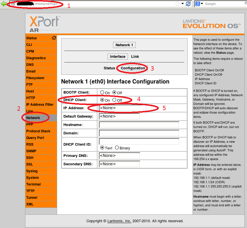
The current CM3 firmware is configured to use DHCP to find it's appropriate IP address. In instances where DHCP is not available a manual IP address can be entered using the following steps
1: Find the current device IP and enter that address into a web browser. The CM3 will default to some IP if not DHCP offers are given, check log files for this address
2: Go to the "Network" page using the link on the side bar
3: Go into the "Configuration"
4: Disable the DHCP client
5: Enter desired IP address

Attachments (1)
-
manualIP.png
(118.4 KB
) - added by 11 years ago.
Manually Entering an IP
Download all attachments as: .zip