
| Version 46 (modified by , 6 years ago) ( diff ) |
|---|
Full-Duplex Wireless using USRP N210
This wiki page contains the tutorial of the first open-access remotely-accessible full-duplex transceiver integrated with the ORBIT testbed. All the source code can be found at this GitHub page.
Description
In this tutorial, we'll use node11-10 in the main grid (equipped with a USRP N210) to transmit and receive a single tone over the air to demonstrate full-duplex wireless capability using the Columbia FlexICoN's Gen-1 Frequency-Flat Amplitude- and Phase-based RF Canceller. Pictures of the FlexICoN RF canceller and node11-10 in the main grid equipped with full-duplex capability are below:
Figure 1: The ORBIT-FlexICoN Full-Duplex Node 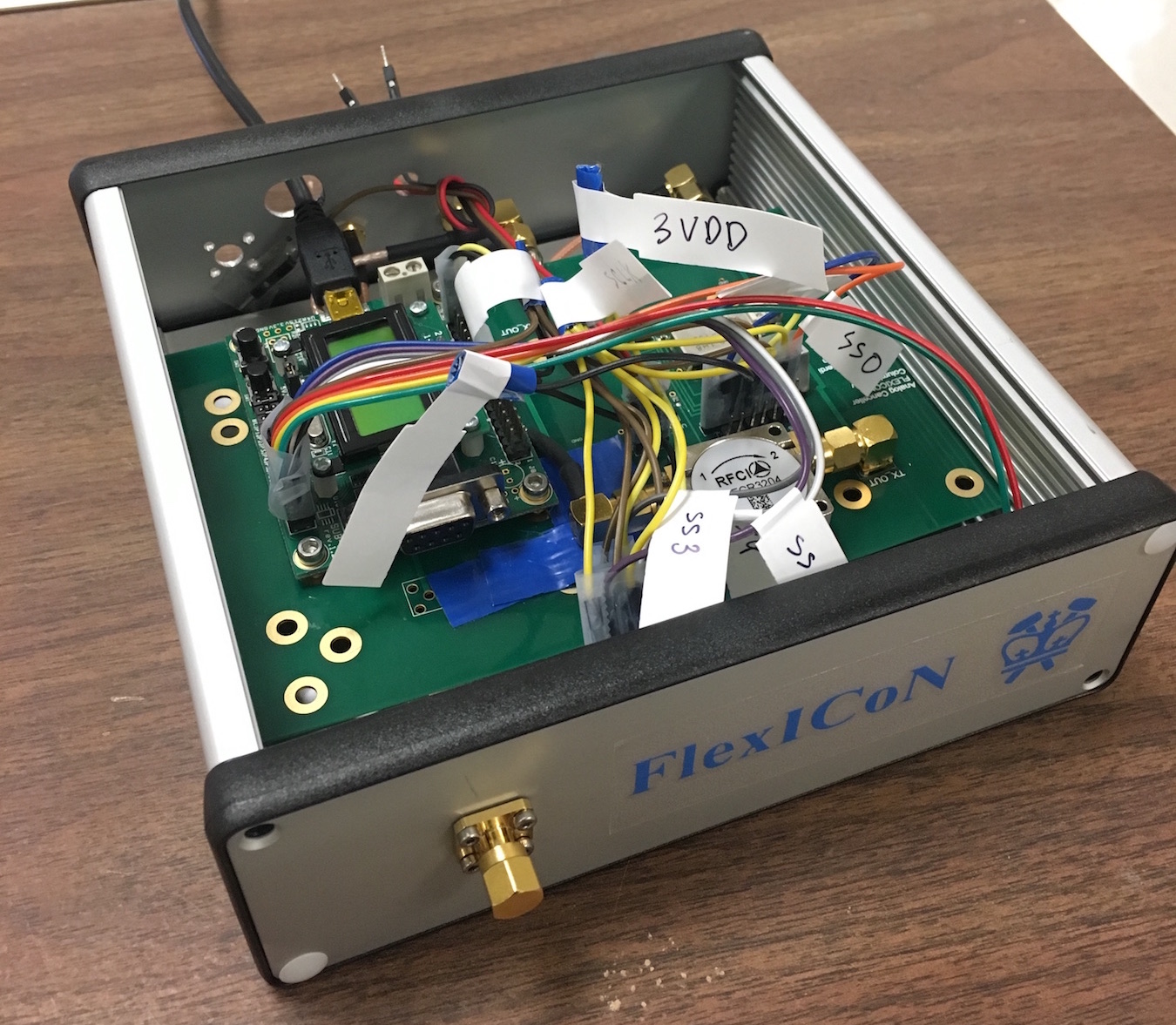
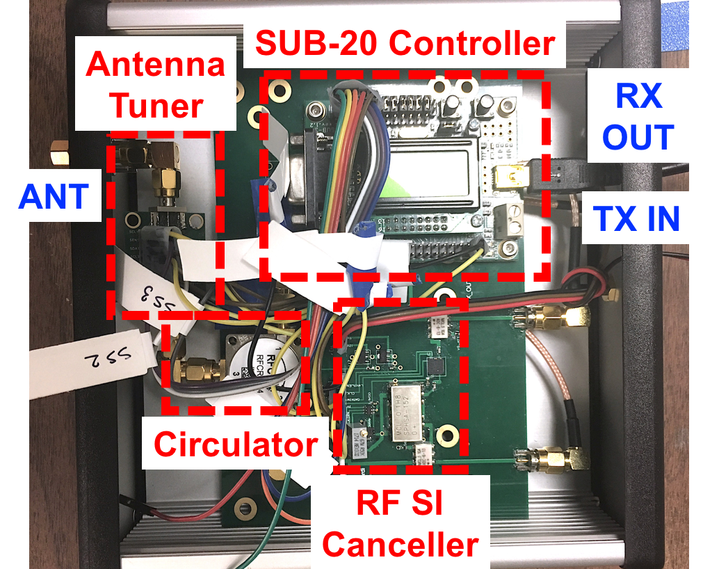
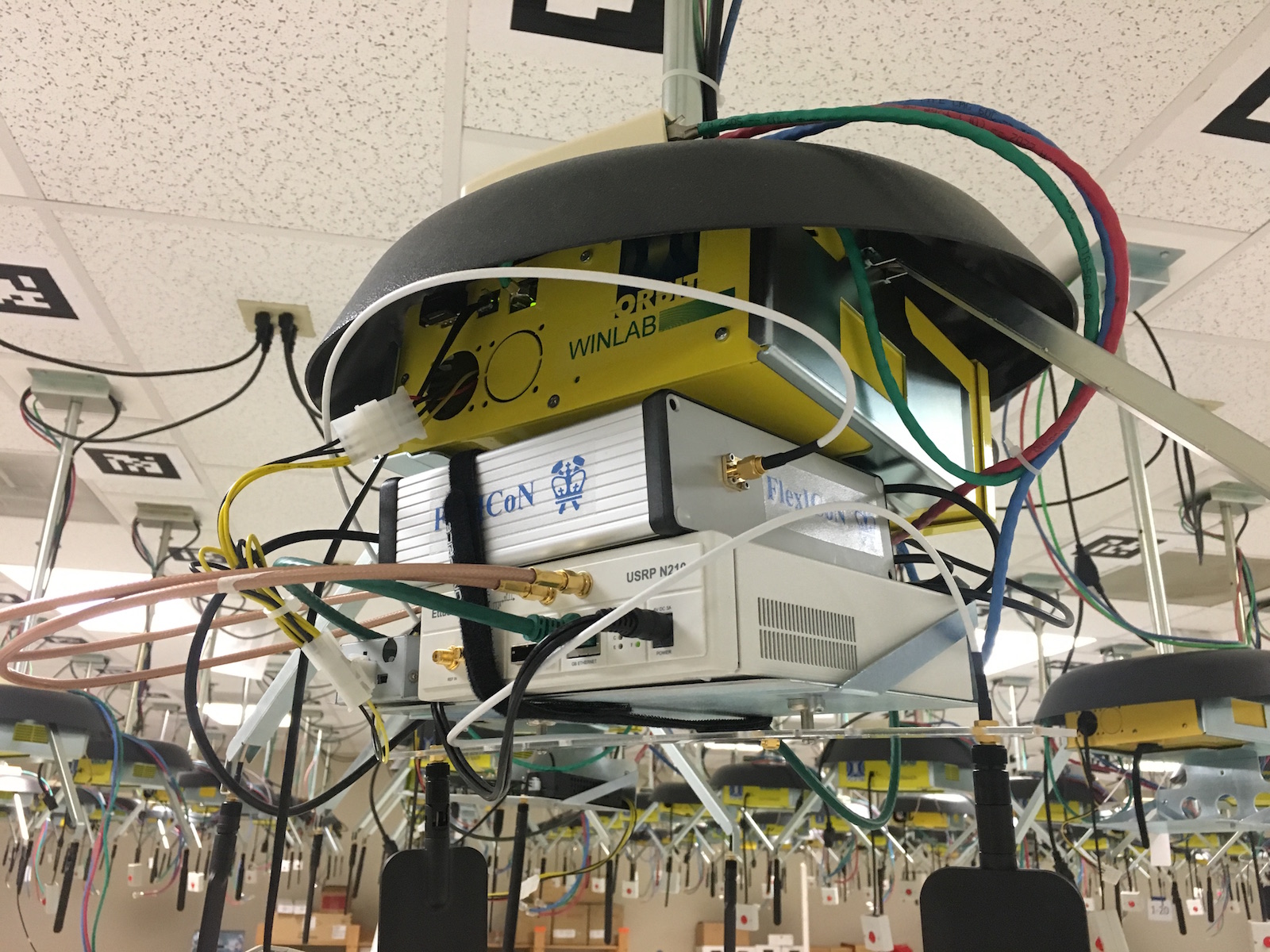
(a) The FlexICoN RF Canceller Box (b) Full-Duplex SDR at node11-10 in the ORBIT grid


Technical Report
For more information, please read:
Tingjun Chen, Mahmood Baraani Dastjerdi, Jin Zhou, Harish Krishnaswamy, and Gil Zussman, “Open-access full-duplex wireless in the ORBIT testbed,” arXiv preprint: 1801.03069 [cs.NI], Jan. 2018. (arXiv report) (INFOCOM'18 Demo Abstract)
Please cite the above arXiv report if you use the hardware. Please email Tingjun Chen (tingjun [at] ee.columbia.edu) if you use (or plan to use) the full-duplex node or if you have any questions.
Updates
[02/28/2018]: PSK examples based on GNU Radio is now available. For more details, please refer to the (INFOCOM'18 Demo Abstract). [01/08/2018]: A UHD benchmark full-duplex transciever example is now available. For more details, please refer to the (arXiv report).
Hardware / Software Resources Utilized
- The Columbia FlexICoN Gen-1 RF Canceller, which is a frequency-flat amplitude- and phase-based RF canceller implemented using discrete components on a PCB. The Gen-1 RF canceller is optimized to have a center operating frequency at 900MHz.
- The source code for the full-duplex transceiver example, which can be found at this GitHub page. We have also build an ORBIT node image
flexicon-orbit-v1.ndzwith all the required software installed to facilitate the experiments. - USRP N210 with node11-10 in the ORBIT main grid.
- SUB-20 is a multi-interface USB adapter for providing popular interfaces between PC (USB host) and different hardware devices. Specifically, we use the SUB-20 SPI module to control and configure the Gen-1 RF canceller (see Fig. 1(a)). The user manual can be found here.
- UHD is already installed with the imaged SDR node.
- The
Eigen C++Library is used for basic algebra used in channel estimation and digital self-interference cancellation. The Eigen releases can be found on the this website. We used the latest stable release Eigen 3.3.4 through our testings and experiments.
Set Up
Before you can access the testbed, you need to make a reservation and get it approved. After receiving the reservation's confirmation (approval) email:
- Login into reserved domain:
ssh username@conslole.grid.orbit-lab.org - Make sure that the full-duplex node is powered down for loading the desired image:
omf tell -a offh -t node11-10 - Load an image on the node (this process can take about a few minutes so please be patient):
omf load -i flexicon-orbit-v1.ndz -t node11-10 - Turn on the node:
omf tell -a on -t node11-10 - Login into the node:
ssh root@node11-10After login into the node, aflexicon_orbitfolder should exist under the home directory ofnode11-10:~/which contains the source code of this example. You can always retrieve the most recently updated code from here.
Run the Experiments
You will need to login into the full-duplex node (by ssh root@node11-10) in two separate terminal windows lo for running the experiment: one for the main full-duplex transceiver UHD program and one for controlling the RF canceller.
In Terminal 1 (UHD)
- Build the example (this is already done in the loaded image):
cd ~/flexicon_orbit/fd_transceiver_simple/uhd/
mkdir build
cd build
cmake ../
make
- Configure the USRP Ethernet interface:
ifconfig eth2 192.168.10.1 netmask 255.255.255.0 up - Check the conection and serial number of the USRP N210:
uhd_find_devices. The serial number should beF331D4. - Run the example with IQ rate
rate, carrier frequencyfreq, TX gaintx-gain, and RX gainrx-gain:cd ~/flexicon_orbit/fd_transceiver_simple/uhd/build/ ./fd_transceiver_simple --tx-args="serial=F331D4" --rx-args="serial=F331D4" --rate 1e6 --freq 900e6 --tx-gain 0 --rx-gain 10
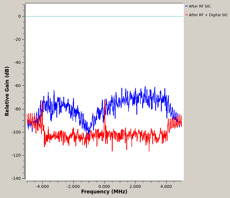
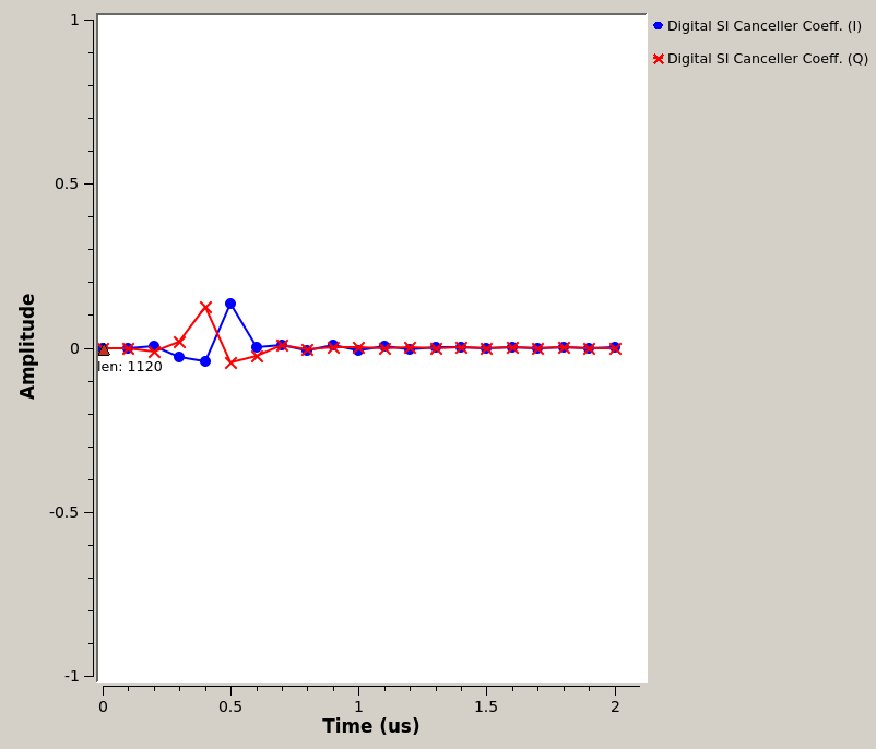
The default sine wave has an amplitudeampl=0.3and wave frequency of 100kHzwave-freq=100e3, which corresponds to a 0dBm TX power level. This terminal window will show the power level at RX baseband, after RF cancellation (before digital) and after digital cancellation, respetively. The UHD program is calibrated with--rx-gain=10, other RX gain values may results in inaccurate power level computation. - An example temrinal output is below:
root@node11-10:~/flexicon_orbit/fd_transceiver_simple/uhd/build# ./fd_transceiver_simple --tx-args="serial=F331D4" --rx-args="serial=F331D4" --rate 1e6 --freq 900e6 --tx-gain 0 --rx-gain 10
linux; GNU C++ version 4.8.4; Boost_105400; UHD_003.010.001.001-0-unknown


Creating the transmit usrp device with: serial=F331D4...
-- Opening a USRP2/N-Series device...
-- Current recv frame size: 1472 bytes
-- Current send frame size: 1472 bytes

.
.
.

Press Ctrl + C to stop streaming...

TX Stream time was: 0 full secs, 0.100064 frac secs

RX Signal Power: -44.093768 dBm (N_FFt = 2048)
RX Res Signal Power: -98.570747 dBm (N_fft = 1024)
Amount of Digital SIC: 54.476979 dB

RX Signal Power: -44.232740 dBm (N_FFt = 2048)
RX Res Signal Power: -98.113147 dBm (N_fft = 1024)
Amount of Digital SIC: 53.880407 dB

RX Signal Power: -43.959299 dBm (N_FFt = 2048)
RX Res Signal Power: -93.406544 dBm (N_fft = 1024)
Amount of Digital SIC: 49.447245 dB

RX Signal Power: -44.179891 dBm (N_FFt = 2048)
RX Res Signal Power: -101.593147 dBm (N_fft = 1024)
Amount of Digital SIC: 57.413256 dB
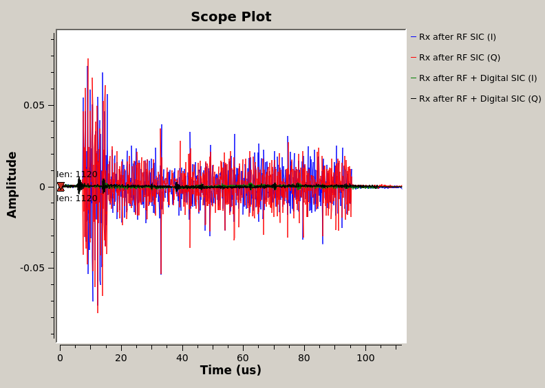
In this example, since the TX power level is at 0dBm, a total amount of around 90dB self-interference cancellation is achieved, of which 45dB is obtained by the Gen-1 RF canceller, and 50dB is obtained by the digital cancellation.
In Terminal 2 (SUB-20)
- Build the RF canceller configuration code (this is already done in the loaded image):
cd ~/flexicon_orbit/fd_transceiver_simple/sub20/
make
- Check the connection to the SUB-20 device using command
lbusb. You should see a XDIMAX devices connected to the USB hub. - Program and configure the RF canceller with the desired values:
cd ~/flexicon_orbit/fd_transceiver_simple/sub20/
./rf_canc_gen1_config PS-CODE ATT-CODE C1-CODE C2-CODE C3-CODE
In particular, thePS-CODE=0,1,2,...,255andATT-CODE=0,1,2,...,127codes are for configuring the 8-bit phase shifter and the 7-bit attenuator of the Gen-1 RF canceller, respectively. It is recommended to useC1-CODE=16, C2-CODE=6, C3-CODE=6, which provides 20dB isolation from the antenna-circulator interface. You can play with the values ofATTandPSuntil you see good cancellation profile (e.g., low residual self-interference power level) in Terminal 1. - An example temrinal output is below:
root@node11-10:~/flexicon_orbit/fd_transceiver_simple/sub20# ./rf_canc_gen1_config 110 30 16 6 6
Started...
Sub20 device found... Serial Number is 48AB
Device Opened!
...Finished programming DAC with value 110!
...Finished programming ATT with value 30!
...Finished programming CAP1 with value 16!
...Finished programming CAP2 with value 6!
...Finished programming CAP3 with value 6!
A Secondary Transmitter Using Node13-8
Once the full-duplex node11-10 is up and running, you can turn on another SDR to transmit to the full-duplex node. Below, we use node13-8 as an example in the 3rd terminal window (Terminal 3).
- Load image, power on, and login into node13-8:
omf tell -a offh -t node13-8
omf load -i baseline-sdr.ndz -t node13-8
omf tell -a on -t node13-8
ssh root@node13-8
- Configure the USRP Ethernet interface:
ifconfig eth2 192.168.10.1 netmask 255.255.255.0 up - Set up a secondary transmitter sending a sine wave at a different frequency (e.g., 200 kHz) than that of the full-duplex node:
./tx_waveforms --args="serial=F331D4" --rate 1e6 --freq 900e6 gain 10 --wave-type SINE --wave-freq 200e3
Now by analyzing the RX baseband data at node11-10, you will observe the received tone at 200kHz while the self-interence tone at 100kHz is cancelled to the USRP noise floor, which is around -90dBm.
Acknowledgements
This work was supported in part by NSF grant ECCS-1547406, DARPA RF-FPGA program, DARPA SPAR program, a Qualcomm Innovation Fellowship, Texas Instruments, and Intel. We thank Steven Alfano, Jelena Diakonikolas, Aishwarya Rajen, Jinhui Song, Mingyan Yu for their contributions to various aspects of the project. We thank Ivan Seskar, Jakub Kolodziejski, and Prasanthi Maddala from WINLAB, Rutgers University, for their help on the integration with the ORBIT testbed. We also thank Kira Theuer and Kendall Ruiz from NI and the NI technical support team for their help.
Attachments (7)
- FlexICoN-gen1-node11-10.jpg (614.4 KB ) - added by 6 years ago.
- FlexICoN-gen1-canceller.jpg (476.4 KB ) - added by 6 years ago.
- FlexICoN-gen1-canceller-label.png (1.2 MB ) - added by 6 years ago.
- flexicon_orbit_grc_ofdm_node.png (142.2 KB ) - added by 5 years ago.
- flexicon_orbit_grc_ofdm_node_tab0.png (103.1 KB ) - added by 5 years ago.
- flexicon_orbit_grc_ofdm_node_tab1.png (37.6 KB ) - added by 5 years ago.
- flexicon_orbit_grc_ofdm_node_tab2.png (35.1 KB ) - added by 5 years ago.