
SB4
Table of Contents
Sandbox 4 consists of 10 nodes along with two LTE and two WiMAX base stations with corresponding BS controllers. The RF connections of these nodes and base stations are wired using low-loss coax cables to a user programmable RF transceiver test system for controlled and repeatable experimentation using various topologies.
Nine of the nodes are equipped with wireless hardware, while the remaining one (node2-1) is intended as an ethernet only device for CUDA processing. To prevent interference, each of the 9 RF nodes is housed in its own Ramsey Electronics RF enclosure that provides 80 dB of isolation.
RF Device Hardware
Each of the RF nodes is equipped with a pair of WiFi devices: one Atheros 5000X mini-PCI card and one Intel 6250 mini-PCIe 802.11/802.16. The antenna connections of these wireless cards are connected through individual 15dB attenuators to a power combiner which connects through a single enclosure access port to the RF test system. This connection is referred to as "WiFi/WiMAX" in subsequent diagrams.
Four of the RF nodes are also equipped with USRP B205mini-i SDR devices. The TX/RX and RX2 ports are connected through individual 15dB attenuators to a 2-way power combiner which connects through the second enclosure access port to the RF test system. This connection is referred to as "USRP" or "SDR" in subsequent diagrams.
Three of the RF nodes are also equipped with USB LTE client adapters for experimentation using commercial clients. The antenna connections of the adapters are connected through individual 15dB attenuators to a 2-way power combiner which connects through the second enclosure access port to the RF test system. This connection is referred to as "LTE Client" in subsequent diagrams.
Possible RF node enclosure setups:
WiFi/WiMAX only WiFi/WiMAX & USRP WiFi/WiMAX & LTE Client 


RF Node enclosure configurations:
Node Name RF Connection 1 RF Connection 2 node1-1 WiFi/WiMAX none node1-2 WiFi/WiMAX none node1-3 WiFi/WiMAX USRP node1-4 WiFi/WiMAX USRP node1-5 WiFi/WiMAX USRP node1-6 WiFi/WiMAX USRP node1-7 WiFi/WiMAX LTE Client node1-8 WiFi/WiMAX LTE Client node1-9 WiFi/WiMAX LTE Client node2-1 none none
In addition to the nodes, two LTE and two WiMAX basestations are available. Due to their high power output, the antenna connections are passed through large value attenuators (and through a 2-way power combiner in the case of the LTE base stations) before connecting to the RF test system.
LTE Base Station WiMAX Base Station 


RF Test System
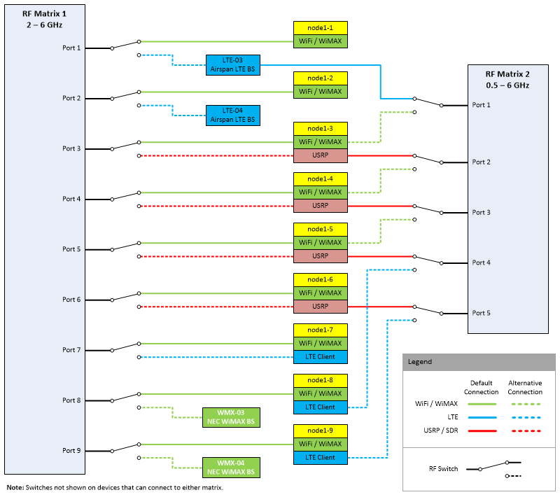
The RF connections of the enclosures housing the nodes as well as the antenna connections of the LTE and WiMAX base stations are all connected to the RF transceiver test system which is composed of an array of RF switches and two attenuator matrices. This system is capable of handling two completely independent topologies: one with up to 9 devices and the other with up to 5 devices, permitting a wide range of experiments to be conducted, including spectrum sharing and multi-homing. Users can configure which devices connect to which matrix and dynamically control the attenuation between each pair of ports using the Instrumentation AM service. The "default connection" referred to in the following tables and diagrams is the default configuration of sandbox 4 when it is "reset" using this service.
The system is designed to provide as many different types of experimental topologies as possible. For example, the user can "swap out" 2 of the nodes for LTE basestations to run handover experiments. Multi-homing experiments can be conducted with WiFi connections running through one matrix and LTE connections through the other matrix. Spectrum sharing experiments can be done with WiMAX and WiFi connections on the same matrix. Commercial LTE base stations and clients can be connected to the same matrix as USRPs running OAI (Open Air Interface). These are just some examples of the possibilities.
IMPORTANT: A device can only be connected to a SINGLE matrix at a time (eg. you can NOT connect the USRP of node1-3 to both matrix 1 and matrix 2. You can however have node1-3 WiFi/WiMAX connected to matrix 1 and node1-3 USRP connected to matrix 2).

Matrix 1:
This is a 9-way full fan-out RF transceiver test system (attenuator matrix) from JFW Industries.
Frequency Range: 2 - 6 GHz
Attenuation Range: 0 - 63 dB in 1 dB steps (in addition to insertion loss and losses from node enclosure connections)
Insertion Loss: 36.0 dB max (31.3 dB typical @ 2 GHz, 33.9 dB typical @ 6 GHz)
Port # Default Connection Alternative Connection 1 node1-1 : WiFi/WiMAX LTE BS (LTE-03) 2 node1-2 : WiFi/WiMAX LTE BS (LTE-04) 3 node1-3 : WiFi/WiMAX node1-3 : USRP 4 node1-4 : WiFi/WiMAX node1-4 : USRP 5 node1-5 : WiFi/WiMAX node1-5 : USRP 6 node1-6 : WiFi/WiMAX node1-6 : USRP 7 node1-7 : WiFi/WiMAX node1-7 : LTE Client 8 node1-8 : WiFi/WiMAX WiMAX BS (WMX-03) 9 node1-9 : WiFi/WiMAX WiMAX BS (WMX-04)
Matrix 2:
This is a 5-way full fan-out RF transceiver test system (attenuator matrix) that was developed in-house.
Frequency Range: 0.5 - 6 GHz
Attenuation Range: 0 - 63.5 dB in 0.25 dB steps (in addition to insertion loss and losses from node enclosure connections)
Insertion Loss: TODO dB max (TODO dB typical)
Port # Default Connection Alternative Connection 1 LTE BS (LTE-03) node1-3 : WiFi/WiMAX 2 node1-3 : USRP node1-4 : WiFi/WiMAX 3 node1-4 : USRP node1-5 : WiFi/WiMAX 4 node1-5 : USRP node1-8 : LTE Client 5 node1-6 : USRP node1-9 : LTE Client
TODO Add S12 traces for various connections.
Trace Replay
Using the Instrumentation AM service, Sandbox 4 can be used to "replay" attenuation and RSSI traces collected in the field or artificially generated through other means, such as the Trace Generation Extension to the METIS II 5G Visualization platform. This capability allows for a repeatable and tightly controlled yet highly dynamic experimentation environment. See the referenced links for more information on usage.
Attachments (6)
- SB4_wifi_only_box.png (9.2 KB ) - added by 7 years ago.
- SB4_wifi_usrp_box.png (37.0 KB ) - added by 7 years ago.
- SB4_wifi_lte_box.png (28.0 KB ) - added by 7 years ago.
- SB4_lte_bs.png (28.2 KB ) - added by 7 years ago.
- SB4_wimax_bs.png (23.6 KB ) - added by 7 years ago.
- SB4_RF_diagram.png (45.3 KB ) - added by 7 years ago.
Download all attachments as: .zip