wiki:Hardware

Version 19 (modified by Ilya Chigirev, 11 years ago) ( diff )

Table of Contents

  1. Hardware
    1. Domains
      1. Grid
        1. Massive-MIMO mini-racks
        2. Servers
        3. Virtual Machines
        4. Noise Injection subsystem
          1. Noise Antennas in the Grid
        5. Support Infrastructure
          1. Synchronized Clock Reference (Octoclock)
      1. Outdoor
        1. Fixed nodes
        2. Mobile nodes
        3. Netbooks
        4. Android Phones
          1. HTC Evo 4G (model: PC36100)
      1. Sandboxes
        1. SB1
          1. RF Connections
        1. SB2
          1. RF Connections
          2. Networking Setup (eth2)
          3. Using images based on baselines before June 12, 2017
          4. Resetting / Rebooting X310's
        1. SB3
        1. SB4
          1. Node to Node RF Path
          2. Node to WiMAX basestation RF Path
        1. SB5
        1. SB6
          1. CR-Kit
          2. Parallela Platform
          3. WARP
        1. SB7
        1. SB8
        1. SB9
          1. Data Switch Connections
          2. Procedures (Edge Core Wedge)
    1. Infrastructure
      1. Servers
      2. Consoles
      3. Switches
        1. NEC IP8800
        2. Pronto 3290
        3. Pronto 3780
      1. Orbit Power Monitoring
        1. Ppower strip monitoring
        2. Node power monitoring
      1. Clock Reference
        1. GPS & PPS/10MHz Clock Reference Distribution System
        2. PTP and NTP Clock Synchronization
    1. Devices
      1. WiFi
        1. Atheros 5212
        2. Atheros 9220
        3. Atheros 9280
        1. Intel 2200
        2. Intel 6250
        1. Broadcom BCM94352HMB
      1. SDR
        1. USRP 1
        2. USRP N210
        3. USRP X310
        4. USRP B210
        5. ORBIT USRP Deployment
          1. USRP Antenna Mounting
          2. USRP Deployment Maps
          3. GRID
          4. SB1
          5. SB2
          6. SB3
          7. SB5
          8. SB7
        1. Nutaq ZeptoSDR
        2. Nutaq PicoSDR
        3. ORBIT Nutaq Deployment
          1. GRID
        1. ZedBoard Based Devices
        1. WARP
        1. Cognitive Radio Kit
        1. Realtek 2832 EZCap
      1. LTE Hardware
          1. eNB Devices
          2. UE Device Locations and SIM info
          3. UE Device Types
        1. Netgear AC341U External LTE Modem
          1. Software Setup
          2. Hardware Setup
      1. Bluetooth
        1. Belkin F8T003 V2
        2. Belkin F8T013
        3. Belkin F8T013uk1
        4. IOGear GBU221
        5. IOGear GBU321
        6. IOGear GBU521
        7. Aluratek ABD2020-R
        8. Zoom Telephonics 4310
        9. Ubertooth One
      1. CUDA
        1. Available Cards
        2. Domains with CUDA Capabilities
        3. Useful Links
      1. ZigBee
        1. Crossbow TELOS-B
    1. Nodes
      1. ORBIT Node (Version 1)
        1. Orbit case 1
      1. ORBIT Node (Version 2)
        1. Orbit case 2
      1. ORBIT Node (version 3)
        1. Main Generation 3 Nodes
          1. LV-67C
          1. LV-67G
          1. LV-67J
        1. Mobile Generation 3 Nodes
          1. LV-67B
          1. LV-67F
          1. LV-67K
        1. Orbit case 3 (COTS)
        1. Assembly
          1. Case Assembly
          1. Mother Board BIOS Settings
      1. ORBIT Node (version 4)
        1. Main Generation 4 Nodes
        2. High Performance Generation 4 Nodes
        3. Large Core Count Generation 4 (SDR) Nodes
        1. Orbit case 4 (COTS)
        1. Assembly
          1. Case Assembly
        1. Debugging notes
      1. ORBIT Mobile Node (version 1)
        1. Hardware
          1. NUC
          2. SDR Front End
        2. Standard 4x4 Case Extension
          1. Battery Operation
          2. Assembly instructions

Table of Contents

    Error: Page Hardware/hInfrastructure does not exist

Hardware

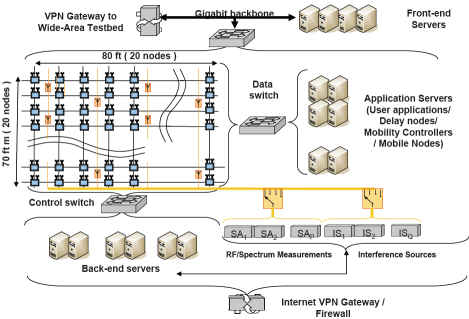
The ORBIT laboratory is comprised of several different test domains in which experimenters can use the hardware provided by WINLAB for use in wireless experimentation. The Orbit grid as illustrated in Figure 1 consists of a multiply interconnected, 20-by-20 grid of ORBIT radio nodes, some non-grid nodes to control R/F spectrum measurements and interference sources, and front-end, application and back-end servers. These servers support various ORBIT services. In addition to the main grid, there are also 9 additional smaller test grids(a.k.a. sandboxes). All this is supported the the back end orbit infrastructure which provides services and control to the test facility.

ORBIT Hardware Block Diagram
Figure 1. ORBIT Hardware.

Each radio node is a PC typically with two 100BaseT Ethernet ports, radio cards and a chassis manager(CM) to control the node. The two Ethernet ports are connected to Data and Control subnet. While Control is used primarily for node access, experiment management and measurement collection, the Data subnet is exclusively available to the experimenter. In addition to the the standard radio cards on most of the nodes, there are many other devices throughout including devices for various communication protocols as well as software radio platforms such as the USRP & USRP2. The full list is found under the devices description page.

Detailed information on the various hardware components that are used to realize the ORBIT testbed can be found by following the links above.

  • Chassis Manager(CM) - Each node in ORBIT is equipped with a chassis manager. This section described the details of how the chassis manager is used and the design on the CM
  • Cases - This section briefly goes over the various enclosures that have been used to house the nodes
  • Assembly - A description of the assembly process for the nodes

Attachments (1)

  • hardware-50.png (75.1 KB ) - added by seskar 10 years ago. ORBIT Hardware Block Diagram

Download all attachments as: .zip

Note: See TracWiki for help on using the wiki.