
| Version 41 (modified by , 7 years ago) ( diff ) |
|---|
SB4
Table of Contents
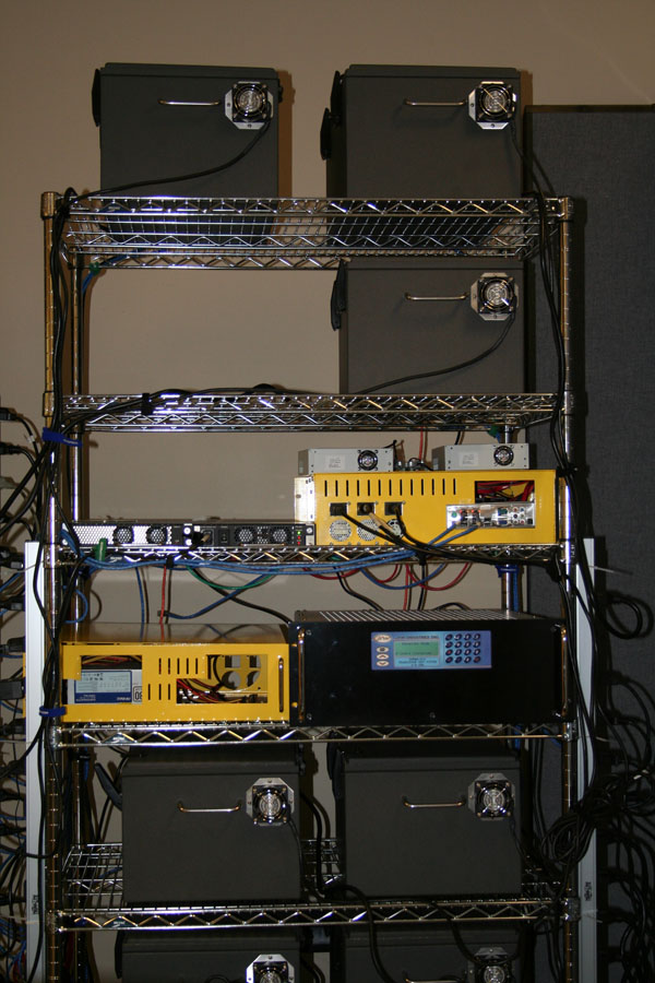
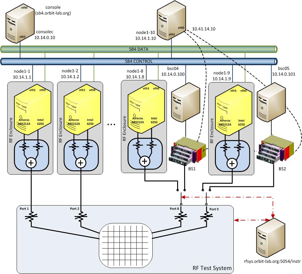
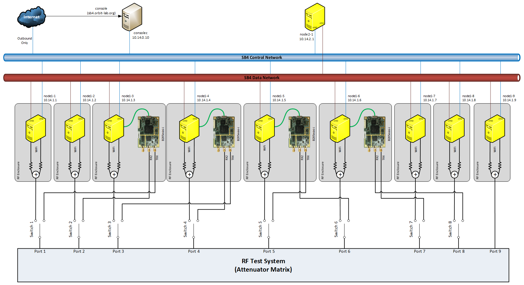
As shown in Figure 1, sandbox 4 consists of 10 nodes and two LTE and two WiMAX basestations and corresponding BS controllers. To prevent interference, each node is housed in Ramsey Electronics RF enclosure that provides 80 dB of isolation. Each of the 9 nodes is equipped with a pair of WiFi devices: one Atheros 5000X mini-PCI card and one Intel 6250 mini-PCIe 802.11/802.16. 4 nodes are also equipped with USRP B205mini-i SDR devices. All of the antenna ports of in each node are connected to a power combiner and fed through the enclosure access port to the outside SMA connector which is wired to one of the input/output ports of the RF Transceiver Test System from JFW Industries. This configuration enables fairly tight control of RF attenuation matrix between the nodes. Four of the RF test system ports are shared between nodes and basestations (node1-1 and node1-2 are sharing their port with LTE baestations while node1-8 and node1-9 are sharing their ports with WiMAX basestations). The topology (including pairwise attenuation between ports and selection switches for node/basestation) is controlled through the OMF based Instrumentation AM.


As can be seen in figure 1, there are a total of nine (9) input/output ports on the transceiver test system. The first 7 input/output ports are connected to nodes 1 thru 7, respectively while the 8th and 9th input/output ports are connect to either nodes 1-8 and 19 or the two Wimax base stations (BS1 and BS2). The selection of devices attached to ports 8 and 9 is controlled by the selDevice command of the Instrumentation AM service.
RF Test System Port Attached device 1 node1-1 2 node1-2 3 node1-3 4 node1-4 5 node1-5 6 node1-6 7 node1-7 8 node1-8 or wimax BS1 9 node1-9 or wimax BS2
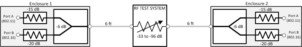
This configuration creates two distinct set of RF paths that are used to create various topologies.
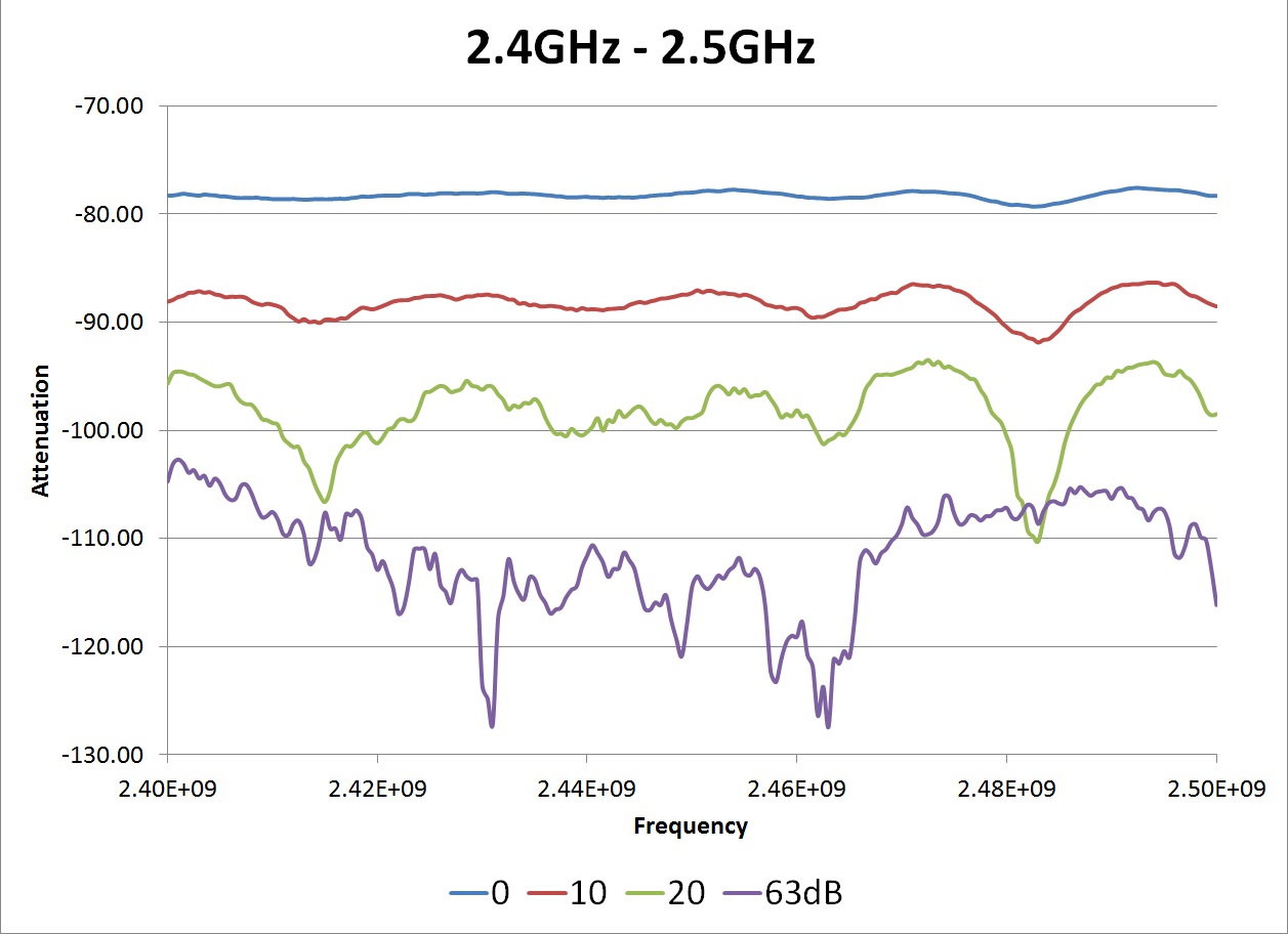
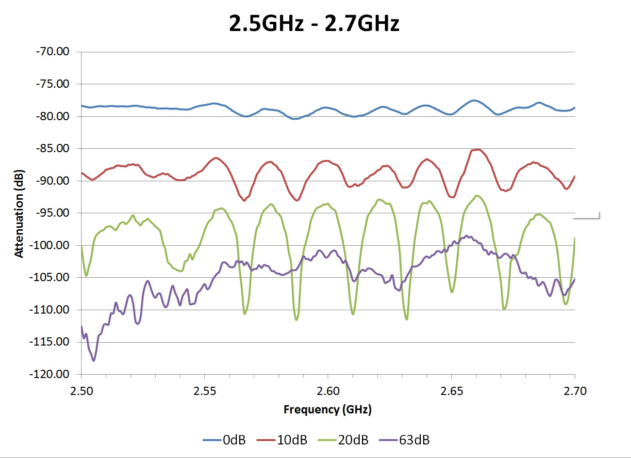
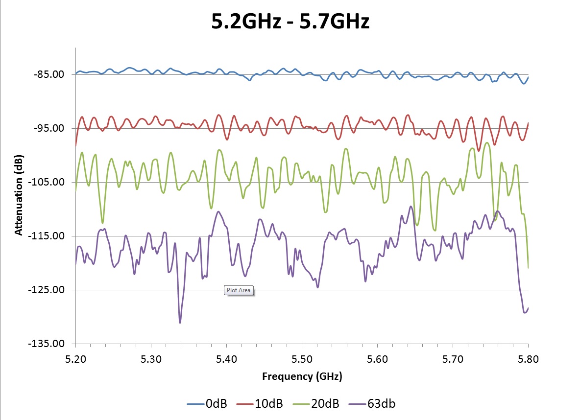
Node to Node RF Path
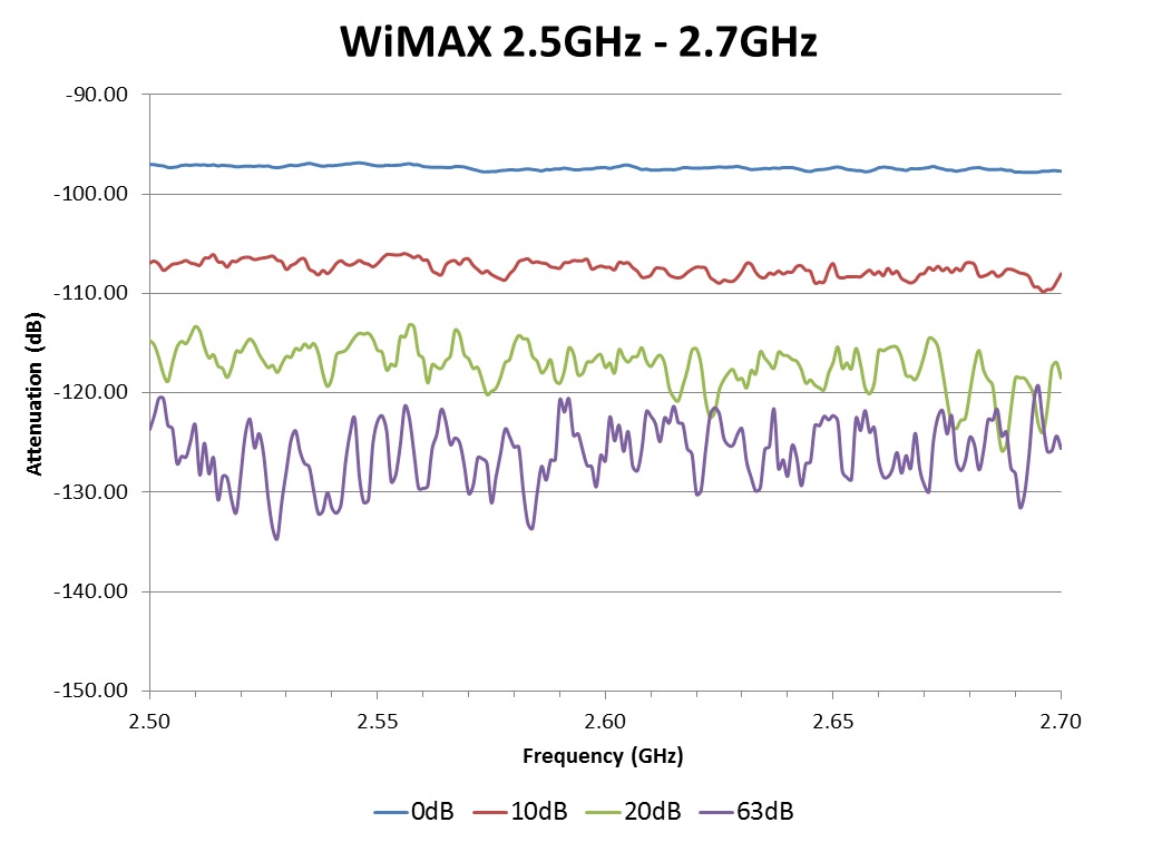
s12 parameters taken with Agilent ENA RF Network Analyzer E5070; instrument dynamic range of 110 dB limits the accuracy of large attenuation results.

 |  | 
|
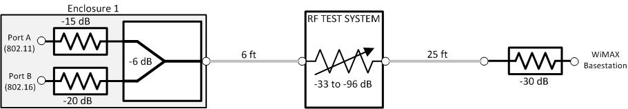
Node to WiMAX basestation RF Path


Attachments (10)
-
IMG_0376.jpg
(154.3 KB
) - added by 12 years ago.
SB4 Photo
-
SB4-Equiv-WiFi.jpg
(27.4 KB
) - added by 12 years ago.
SB4 RF path enclosure-to-enclosure
-
S12-A-24.jpg
(142.8 KB
) - added by 12 years ago.
SB4 path A transfer - 2.4 GHz
-
S12-A-25.jpg
(166.3 KB
) - added by 12 years ago.
SB4 path A transfer - 2.5 GHz
-
S12-A-52.jpg
(150.0 KB
) - added by 12 years ago.
SB4 path A transfer - 5.2 GHz
-
S12-B-25.jpg
(113.7 KB
) - added by 12 years ago.
SB4 path B transfer - 2.5 GHz
-
SB4-Equiv-WiMAX.jpg
(20.3 KB
) - added by 12 years ago.
SB4 RF path enclosure-to-basestation
-
SB4.jpg
(124.4 KB
) - added by 9 years ago.
SB4 Block Diagram
- 50PMA-012_specsheet.pdf (22.1 KB ) - added by 5 years ago.
- SB4.png (207.8 KB ) - added by 4 years ago.
Download all attachments as: .zip