
| Version 16 (modified by , 12 years ago) ( diff ) |
|---|
Table of Contents
SB4
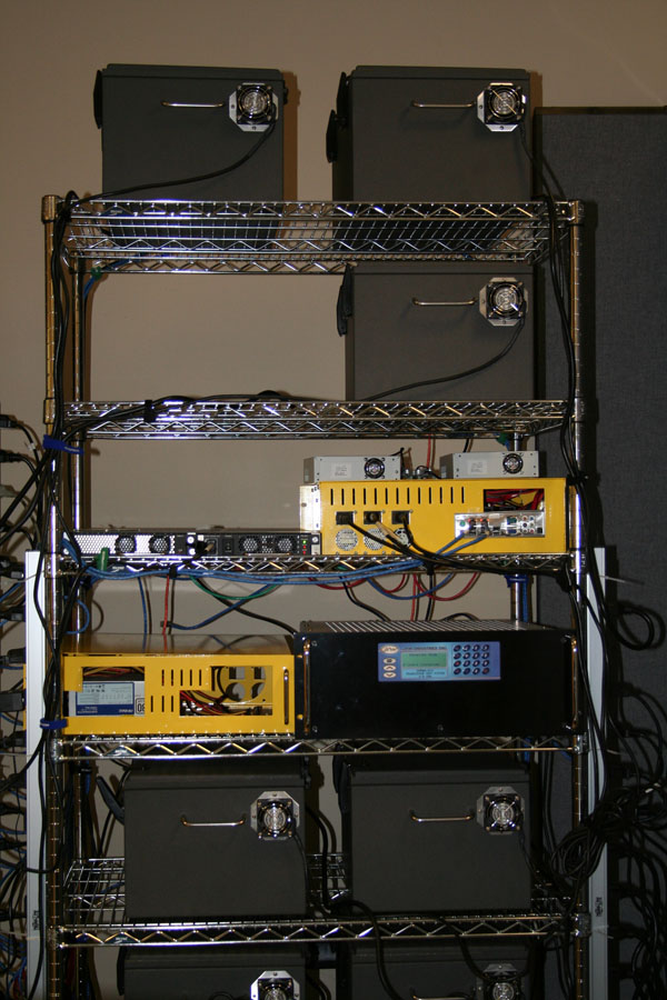
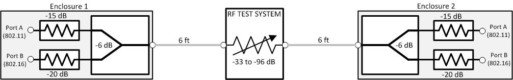
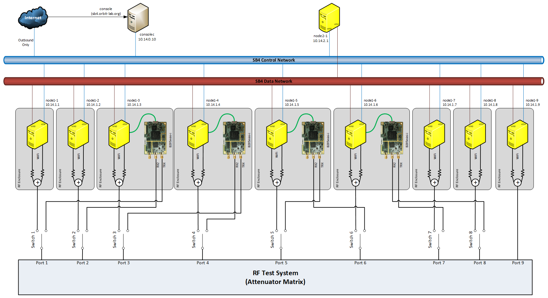
As shown in Figure 1, sandbox 4 consists of 8 nodes and a WiMAX subsystem that consists of a basestation and a controller. To prevent interference, each node is housed in Ramsey Electronics RF enclosure that provides 80 dB of isolation. Nodal wireless devices (Atheros 5000X mini-PCI card and Intel 6250 mini-PCIe 802.11/802.16) are connected to a power combiner and fed through the enclosure access port to the outside SMA connector which is wired to one of the input/output ports of the RF Transceiver Test System from JFW Industries. This configuration enables fairly tight control of RF attenuation between the nodes. The topology is controlled through the OMF based Instrumentation AM.


Attachments (10)
-
IMG_0376.jpg
(154.3 KB
) - added by 12 years ago.
SB4 Photo
-
SB4-Equiv-WiFi.jpg
(27.4 KB
) - added by 12 years ago.
SB4 RF path enclosure-to-enclosure
-
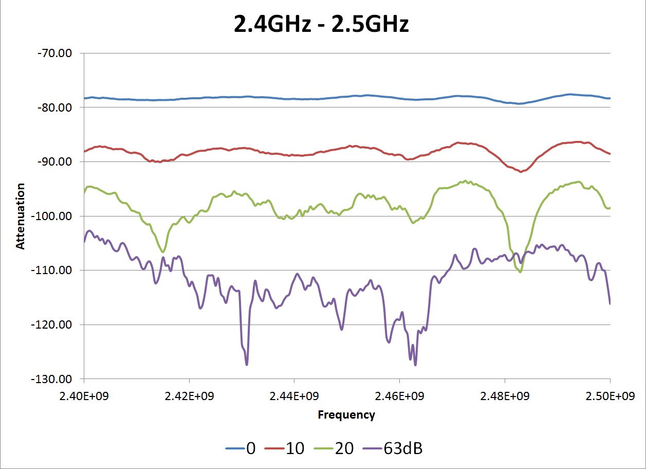
S12-A-24.jpg
(142.8 KB
) - added by 12 years ago.
SB4 path A transfer - 2.4 GHz
-
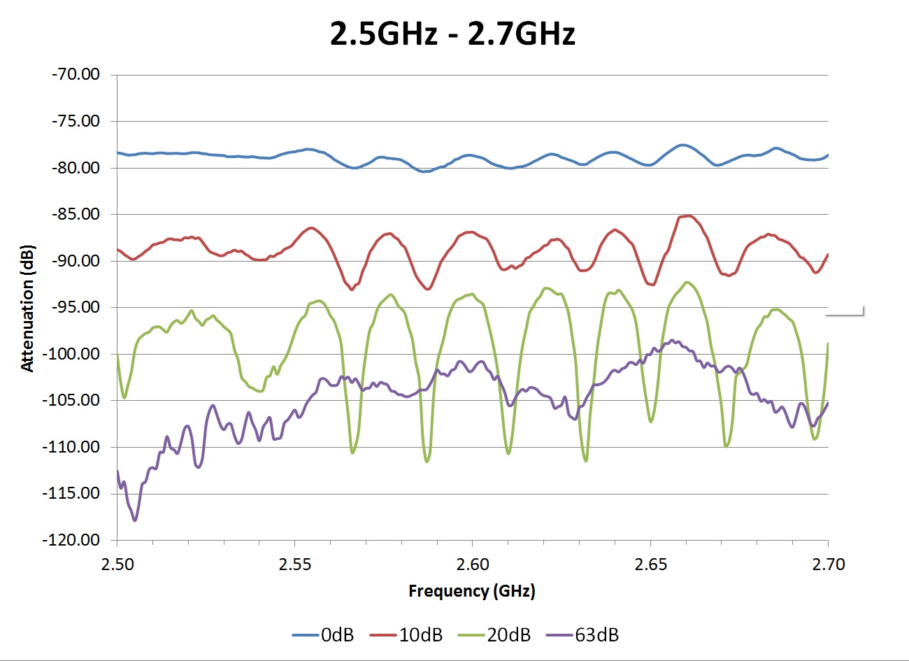
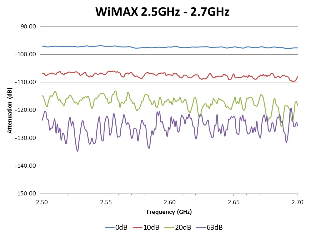
S12-A-25.jpg
(166.3 KB
) - added by 12 years ago.
SB4 path A transfer - 2.5 GHz
-
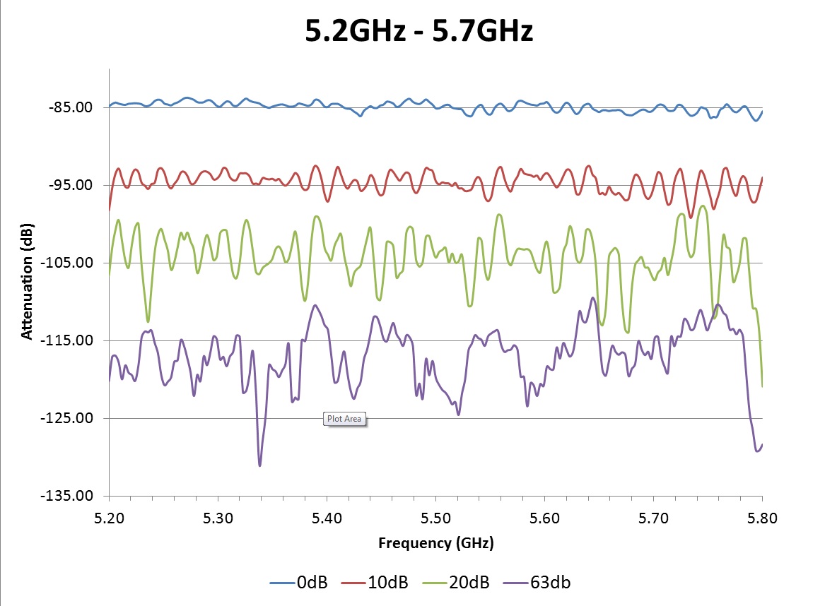
S12-A-52.jpg
(150.0 KB
) - added by 12 years ago.
SB4 path A transfer - 5.2 GHz
-
S12-B-25.jpg
(113.7 KB
) - added by 12 years ago.
SB4 path B transfer - 2.5 GHz
-
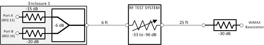
SB4-Equiv-WiMAX.jpg
(20.3 KB
) - added by 12 years ago.
SB4 RF path enclosure-to-basestation
-
SB4.jpg
(124.4 KB
) - added by 9 years ago.
SB4 Block Diagram
- 50PMA-012_specsheet.pdf (22.1 KB ) - added by 5 years ago.
- SB4.png (207.8 KB ) - added by 4 years ago.
Download all attachments as: .zip
Note:
See TracWiki
for help on using the wiki.